Pressure Systems, Inc. 98RK-1 & 9816 User’s Manual©
Page 128 www.PressureSystems.com
5.1.6.5 Solenoid Valve O-Ring Replacement
The following is a step-by-step procedure to replace the internal solenoid valve O-rings in a
Model 9816 Intelligent Pressure Scanner. The modules contain two internal solenoid valves.
(1) Disassemble the module as described in Section 5.1.2.
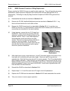
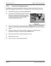
(2) Remove the two (2) Allen-head screws that secure
the solenoid manifold to the module top guide rail.
Carefully move the solenoid manifold assembly to
one side for easier access. Be careful not to
crimp the attached nylon tubing.
Figure 5.11
Solenoid Valve O-Ring Replacement
(3) Remove the solenoid valve by unscrewing the two Phillips-head screws on top of the
solenoid, and following the procedures described in Section 5.1.5. Gently lift it out of the
module.
(4) Remove and replace the O-rings (red) (PSI part number 61-02-3063) needing
maintenance using the procedure described in Section 5.1.6.1.
(5) Replace the solenoid valve and gently tighten the screws.
(6) Reassemble the module.
(7) Test your scanner to ensure proper operation.


