


Extron • Matrix 3200/6400 Series • User’s Manual
Chapter 2 • Installing the Matrix 3200/6400 Video Switcher
2-2
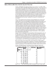
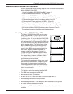
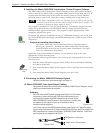
2. Setting BME Addresses
Each BME must be set to a unique address of 0 - 5 using a push-button switch
located on the rear panel (see Figure 2-2.B, Item 1). BME #0 will be the Main
Controller and may be any module except the Sync module.
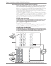
3. Connecting the BME COMM interconnecting cable(s)
If there is more than one BME, the BME COMM connectors
must all be connected together in daisy chain fashion using
Extron supplied RJ-11 telephone cable (Figure 2-2.A). The
chain begins at the BME COMM OUT connector of BME #0
(See Item 2 in Figure 2-3.A) and connects to the BME COMM
IN connector of the closest BME, that BME’s BME COMM OUT connector is
then connected to the next closest BME if necessary. Repeat this process until
all BMEs are connected (No BME will have two empty BME COMM connectors).
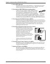
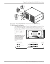
4. Connecting the RS-232/RS-422 Cable to BME #0
Connect the cable from the Host PC computer serial port to the RS-232/RS-422
connector on the rear panel of BME #0 as shown in Figure 2-3.A on the next page
(Item3). After the BME(s) have been virtualized, they can be controlled through
this connection using a PC Host or from a touch screen or any other user-
supplied controlling device, such as AMX, Crestron, etc., that is capable of
generating the proper commands.
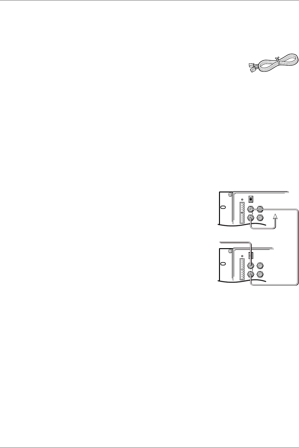
5. Connecting the External Vertical Interval Sync Cables
Matrix 3200/6400 video switchers can use an
external sync signal during the vertical interval.
The required external sync signal is essentially
a composite sync signal from a black burst
generator or a time base corrector. The
illustration to the right shows the sync
connections. The IN connector receives the
external sync timing signal. The OUT connector
allows the signal to be passed on to another
video device if required.
If there is no external sync, the switcher will
switch inputs at any time during the vertical
scan.
6. Connecting the AC Power Cable(s) to the BME(s)
Each BME has its own internal power supply. Connect an AC Power cord to the
AC power receptacle on each BME (Item 4 in Figure 2-3.A). Connect the power
cord plug to an AC power source.
7. Applying AC Power to the BME(s)
Each BME has a power ON/OFF toggle switch on the rear panel just above the
AC power cord receptacle. BME #0 must be powered ON at the same time or
after all other BMEs are ON. Press each power switch to the ON (1) position, Go
to 7A on Page 2-3.
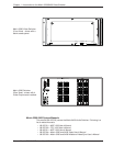
Figure 2-2.A
RJ-11 Cable
MKP COMM.
A
B
C
D
E
A
B
C
D
E
BME
ADDRESS
4
-
+
MKP COMM.
A
B
C
D
E
A
B
C
D
E
BME
ADDRESS
4
-
+
1IN
SYNC
OUT
2
1IN
SYNC
OUT
2
Sync Timing Source
To Next
Device
(if required)
Figure 2-2.B