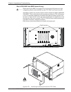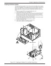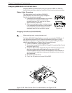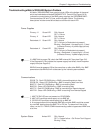
Extron • Matrix 3200/6400 Series • User’s Manual
Chapter 5 • Upgrades and Troubleshooting
MATRIX 6400
VIDEO
POWER SUPPLIES COMMUNICATIONS
PRIMARY TX
RS232 BME REMOTE
SYSTEM
STATUS
REDUNDANT RX
DIAGNOSTICS
+
V
-
V
MATRIX 6400
VIDEO
POWER SUPPLIES COMMUNICATIONS
PRIMARY TX
RS232 BME REMOTE
SYSTEM
STATUS
REDUNDANT RX
DIAGNOSTICS
+
V
-
V
MATRIX 6400
VIDEO
POWER SUPPLIES COMMUNICATIONS
PRIMARY TX
RS232 BME REMOTE
SYSTEM
STATUS
REDUNDANT RX
DIAGNOSTICS
+
V
-
V
MATRIX 6400
AUDIO
POWER SUPPLIES COMMUNICATIONS
PRIMARY TX
RS232 BME REMOTE
SYSTEM
STATUS
REDUNDANT RX
DIAGNOSTICS
+
V
-
V
RGB
MUTE
AUDIO
MUTE
5-10
5. Connect the RS-232/RS-422 cable to the serial port of BME #0. (Page 2-2)
6. Connect the AC Power cable(s) to the BME(s). (Page 2-2)
7. Apply AC power to the BMEs and Verify Normal Power-Up. (Page 2-2)
8. Do the steps under “After Hardware Changes” on Page 5-12.
9. Connect cables to BMEs (video, sync and/or audio cables). (Page 2-4)
The procedure for adding a Video and/or an Audio BME follows.
Adding a Video and/or an Audio BME
Matrix 3200/6400 Video BME(s) and/or a Matrix 6400 Audio BME may be
installed in a rack with an existing Matrix 3200/6400 Video system, or in a
different location. BMEs may be separated by up to 12 feet and rack mounting is
NOT required. If the Video and/or Audio BME(s) are going to be rack mounted
with other BMEs, they may be mounted in any order within a rack or cabinet.
There are no restrictions to the order in which BMEs may be mounted relative to
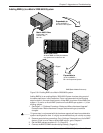
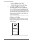
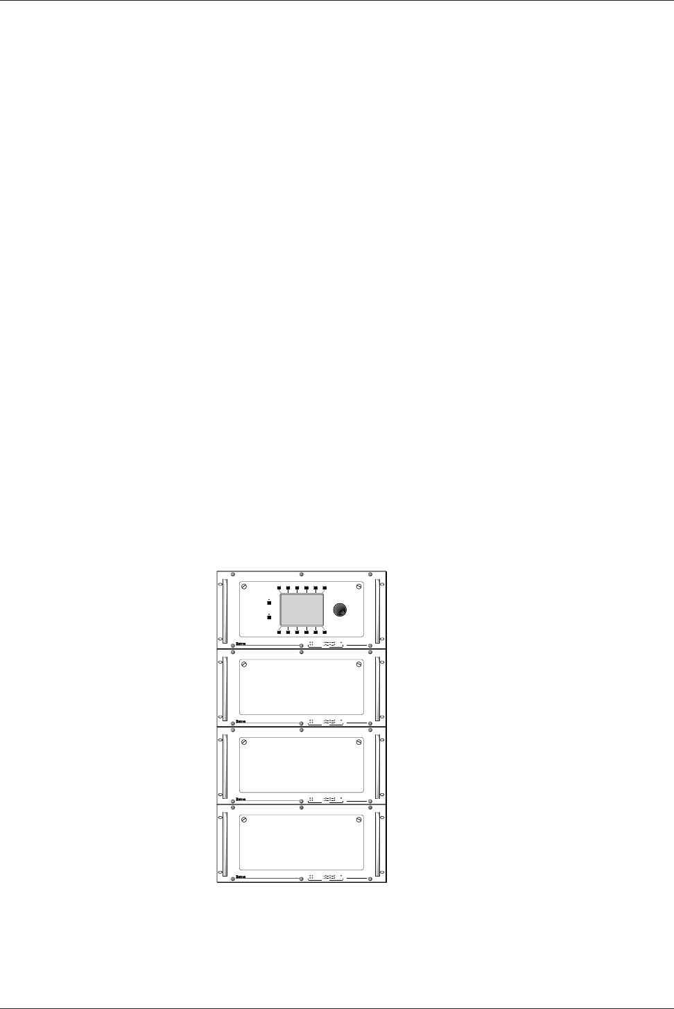
each other. Logically, the BME addresses in a system such as the one shown in
Figure 5-10.A would be set to 0 - 5 sequentially from top to bottom, however, a
different order is acceptable and will not impact system operation in any way.
Equipment location within a room should be given careful consideration. Poor
planning, with the number of cables involved, could result in a cluttered
appearance. Power requirements and
the amount of heat exhaust from the system should be taken into consideration.
The following restrictions apply to installing BMEs.
• One BME must be assigned as BME#0.
• A BME with an FPC 1000 must be BME#0.
• Address assignments must not skip numbers.
• Address assignments of 0 - 5 are accepted, BMEs w/address 6-9 are ignored.
• A Matrix 3200/6400 Video system is limited to a maximum of 3 Video and one
Audio BME(s).
See Page 2-1 for other BME restrictions.
Return to step 3 above.
Figure 5-10.A Example of a Matrix 3200/6400 Video rack-mounted system


