


DTP T EU 332, DTP T EU 232, DTP T MK 332, and DTP T MK 232 • Installation and Operation 7
Rear Panel and Side Panel Features
Top
Side Rear
DTP
HDBT
RESET
CONFIG
1.0 A MAX
SIGLINK
OUT
Tx Rx GTxRxGTx Rx
RS-232
OVER TP
RS-232
POWER
12V
IR
REMOTE
B
A
C
G
FED
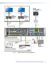
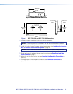
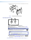
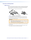
Figure 3. Rear Panel and Side Panel Features
A
TP function switch (see below)
E
Remote RS-232 port (see page 8)
B
Configuration port (see below)
F
Power connector (see page 8)
C
TP connector (see page 8)
G
Reset button (see page 8)
D
Over TP RS-232 and IR port port (see page 8)
A
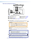
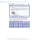
TP function switch — If the receiving device is in the Extron DTP series, set this
HDTP
DTP
switch to the DTP position. For an HDBaseT-enabled receiver type, set this switch
to the HDBT position. This switch tailors the output signal as follows:
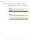
ATTENTION:
• Position this switch BEFORE connecting the appropriate device to the TP
connector. Failure to comply can damage the endpoint.
• Positionnez le sélecteur AVANT de connecter l’appareil approprié au
connecteur TP. Ne pas respecter cette procédure pourrait endommager le
point de connexion.
HDBT position — The TP output consists of HDMI with embedded audio plus RS-232
and IR.
DTP position — TP output consists of HDMI with embedded audio, analog audio,
RS-232 and IR, and remote power.
NOTES:
• When the switch is in the HDBT position, the transmitter and receiver each
requires a local 12 VDC power supply.
• When the switch is in the DTP position, one 12 VDC power supply,
connected to either the transmitter or the receiver, can power both units.
B
Config port — Connect a host device to the USB mini B configuration port.
CONFIG
NOTE: A Configuration port connection and a Remote RS-232 port connection can
both be active at the same time. If commands are sent simultaneously to both, the
command that reaches the processor first is handled first.