


DTP T EU 332, DTP T EU 232, DTP T MK 332, and DTP T MK 232 • Installation and Operation 13
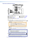
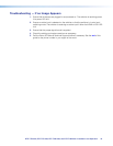
VGA Connector Wiring
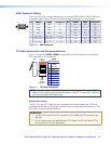
The 15-pin HD (VGA) universal analog input port accepts RGB (RGBHV, RGBS, RGsB) and
component video. Figure 10 shows the pinout for each format type on the connector.
Pin RGBHV
1
Red
Green
R-Y
Y
Red return R-Y return
Green return Y return
Blue return B-Y return
NC NC
Blue B-Y
RGBS Component
2
Red
Green
NC
6 Red return
7 Green return
8 Blue return
3 Blue
15
11
15
4, 5
Pin RGBHV RGBS Component
9
10
14
15
11
12
13
NC
Ground
V sync
NC
H sync
NC
Ground
NC
NC
NC NC
C sync
NC NC
NC
NC
NC
NC
NC
NC
NC
Figure 10. VGA Connector
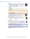
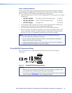
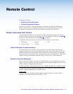
TP Cable Termination and Recommendations
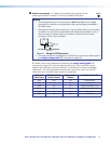
Figure 11 details the TIA/EIA T 568B wiring standard. Use this standard to terminate the
DTP cable with RJ-45 connectors.
5
Pin
1
2
3
6
7
8
4
Side
12345678
Insert
Twisted
Pair Wires
Pins:
RJ-45
Connector
Wire color
White-green
Green
White-orange
White-blue
Orange
White-brown
Brown
Blue
TIA/EIA T
568 B
Figure 11. TP Cable Termination
NOTE: Do not use Extron UTP23SF-4 Enhanced Skew-Free AV UTP cable or STP201
cable to link the switching transmitter and receiver. The DTP T EU and DTP T MK units
do not work properly with these cables.
Supported cables
The DTP T EU and DTP T MK units are compatible with shielded twisted pair (STP) and
unshielded twisted pair (U/UTP) cable. However, Extron strongly recommends that you use
STP cable to achieve best performance.
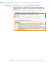
ATTENTION:
• To ensure FCC Class A and CE compliance, STP cables and STP connectors are
required.
• Afin de s’assurer de la compatibilité entre FCC ClasseA et CE, les câbles STP et
les connecteurs STP sont nécessaires.