


Fiber Optic Test Meters • Operation 5
FPM 101 Power Meter — Controls and Connections
λ
Ref
dBm
dB
0000
0.00
WAVE ID
nm
Hz
µW
dB
0000
0.00
nm
Hz
µW
dB
µW Set
FPM 101
FIBER POWER METER
POWER
f
e
d
a
b
c
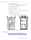
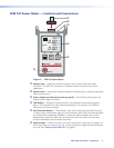
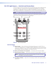
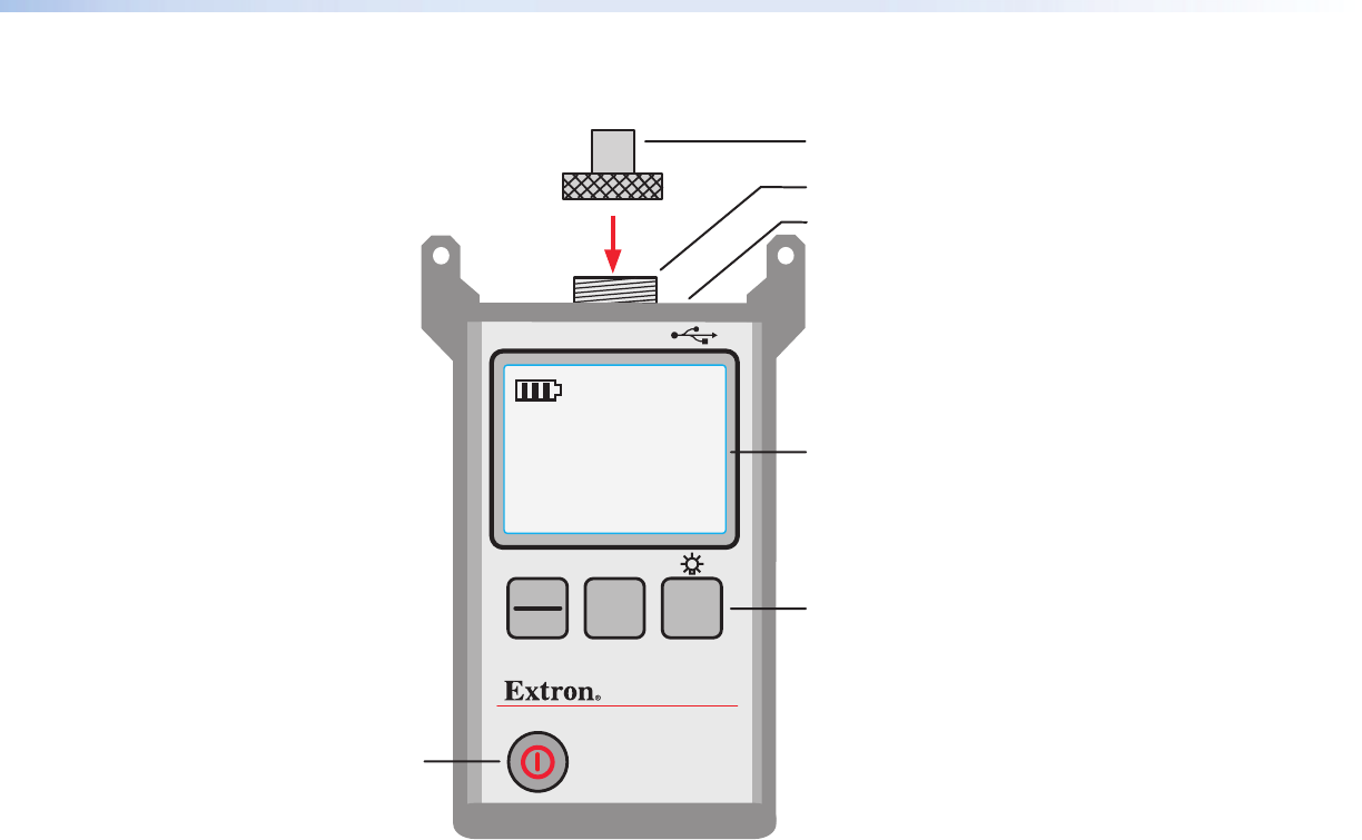
Figure 3. FPM 101 Power Meter
a Adapter Cap — Adapts the thread-on optical input to various fiber optic cable
connectors. The FPM 101 includes an LC adapter cap which matches most Extron
applications.
b Optical input — Accepts the thread-on adapter cap allowing you to quickly change the
fiber optic connector.
c Power adapter port (located on the top panel) — Mini-USB Type B connector for
external power supply connection
d LCD Display — Displays the various values of the selected mode including power in
dBm or uW, insertion loss in dB, calibrated wavelength, tone signal in Hz, WAVE ID,
references, and battery strength.
e Dual Function Buttons — Three buttons, each with primary and secondary functions,
to select power measurement type, (λ), set the reference level, (Ref), and manually select
the measurement wavelength, (dB/dBm). A press and release activates the function
designated by the button label. Press and hold the button to activate the secondary
function indicated by the text above the button.
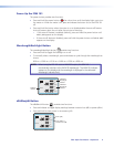
f Power Button — When the meter is off, press and hold for a short time to toggle it on.
When the meter is on, press to turn off, or press and hold to toggle the auto-off feature
on or off (see “Power Up the FPM 101” on page 6).