


Fiber Optic Test Meters • Operation 12
Testing Fiber Optic Links
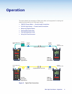
Multimode or singlemode links are easily measured using the FPM 101 power meter and
FLS 101 light source. Two reference cables, transmit and receive, are required. Before an
unknown fiber link can be measured, the insertion loss of the two reference cables must first
be verified to be less than 0.75 dB.
Test the Transmit Reference Cable:
1. Turn on the FPM 101 power meter and FLS 101 light source. Allow the light source to
stabilize for a minimum of two minutes prior to taking measurements.
2. Set the desired measurement wavelength on the FLS 101 light source, (see “Output
Wavelength Selection” on page 10).
a. When using the WAVE ID feature, the FPM 101 power meter reads the wavelength
automatically.
b. If not using WAVE ID, set the FPM 101 to the same wavelength as the FLS 101, (see
“Wavelength/Backlight Button” on page 6).
3. Select and prepare the transmit reference cable. The fiber type of the reference cable
must match the fiber type of the link to be tested.
a. MM: Wrap and secure the reference cable five times around the included mandrel.
b. SM (TIA testing only): Form and secure a 1.2 inch (30 mm) diameter loop in the
reference cable.
NOTE: Clean both ends of the transmit reference cable before proceeding.
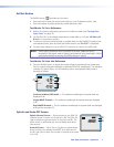
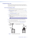
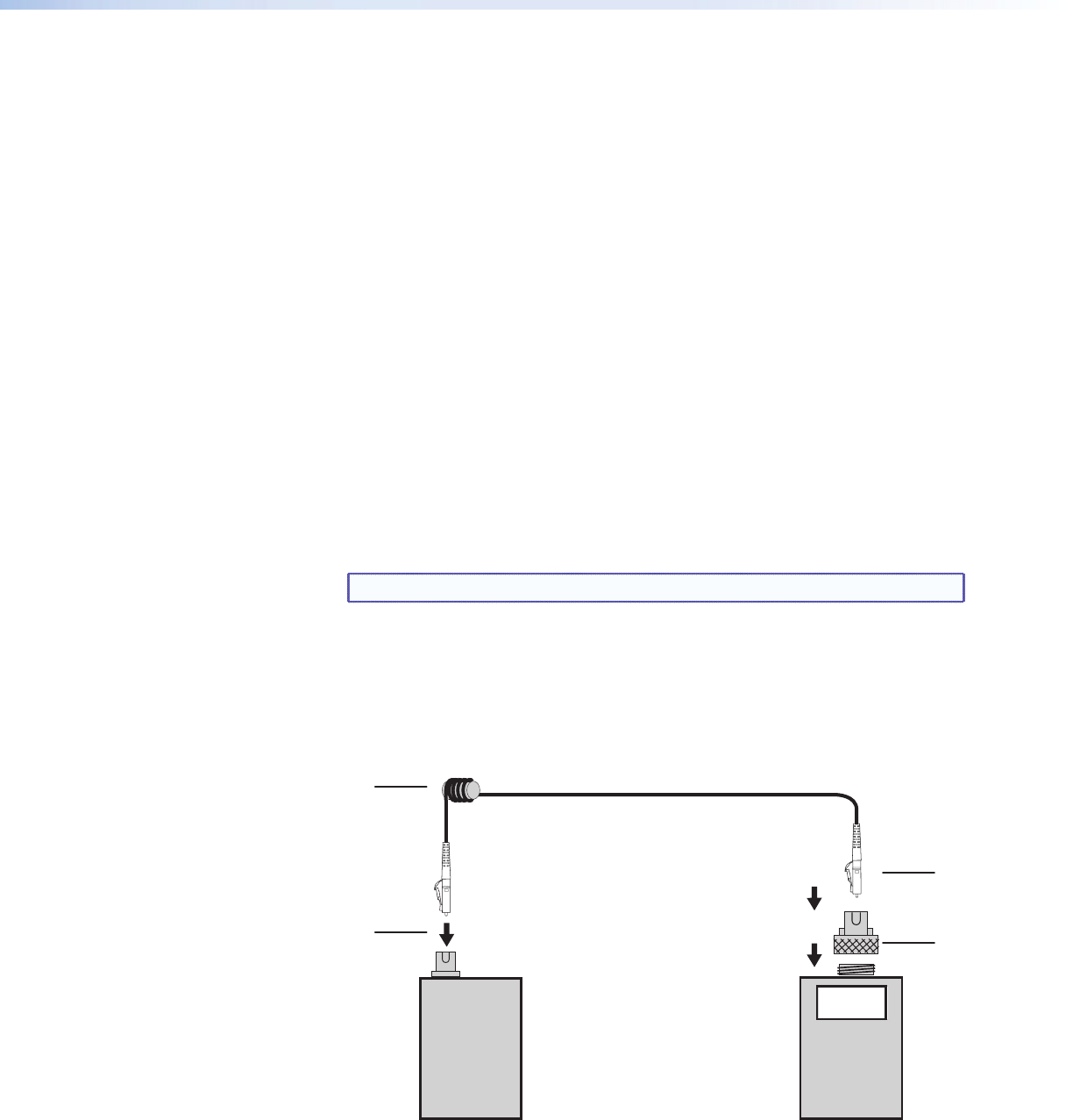
4. Connect the transmit reference cable to the FLS 101 output port (MM or SM).
5. Mount an adapter cap on the power meter. The adapter cap must match the free
connector on the transmit reference cable.
6. Connect the free end of the reference cable to the FPM 101. If necessary, press the
dB/dBm button to display optical power in dBm, (see “dB/dBm/μW Button” on
page 6).
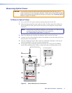
FLS 101 FPM 101
-20 dB
c
d
f
e
Transmit Reference Cable
MM: Mandrel Wrap
(shown), or
SM: 1.2" (30 mm)
Dia Loop
Figure 7. Transmit Reference Cable Connection