


Fiber Optic Test Meters • Operation 16
Using the Tone Generator
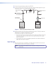
The tone generator is used for fiber identification when an installer is faced with multiple
unmarked links and the cable ends are not readily accessible by a single technician or are far
removed from one another. The tone is inserted by the light source at one end of the link
and identified at the other using the tone feature of the FPM 101.
In new installations, the link ends can be identified with the FLS 101 and FPM 101 using the
WAVE ID feature and simply looking for the active link among the inactive links. However,
in larger bundles that may have links carrying live data traffic, the tone generator in the
FLS 101 can be used to identify spare links. The FPM 101 can differentiate between live
traffic on fibers and the 2 kHz test tone generated by the FLS 101 to ensure a live fiber is not
cut or disconnected causing a disruption of critical services.
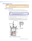
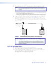
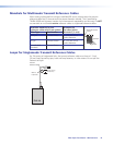
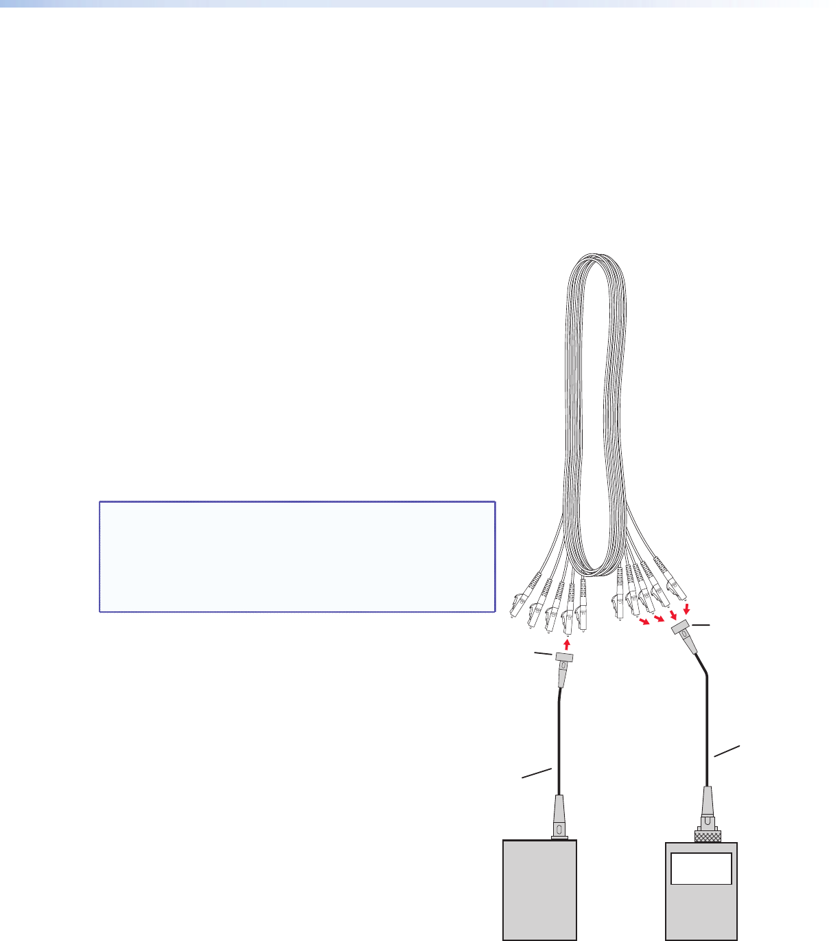
FLS 101 FPM 101
2000 Hz
Coupler
Tr
ansmit
Ref
erence
Cab
le
Receive
Reference
Cable
Coupler
1550 nm
19.46 dBm
Figure 14. Tone Identification Connections
Mark the cable ends for reference.
Clean the connectors and couplers often.
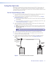
To Quickly Identify a Fiber Optic Link
1. Connect the light source to one end of the link to
be identified. Use the appropriate reference cable
and coupler.
2. Select the 1550 nm wavelength using the SM
button, then turn on the 2 kHz tone by pressing
the tone button. The tone indicator LED lights.
3. On the other end of the link, if the bulkhead is
not accessible, unplug the cables one at a time
and connect them into the receive reference cable
using a coupler. The cable that causes the 2000 Hz
display to light is the desired cable.
NOTE: Cables with live data traffic are identified by their
wavelength and signal strength but they do not light
the tone display.
Identifying wavelengths is not instantaneous. Always
wait a few moments for the FPM 101 to identify the
signal.