


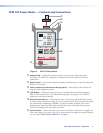
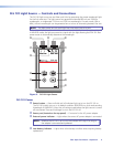

Fiber Optic Test Meters • Operation 13
7. The normal range is -20 dBm for multimode cables, 0 dBm for singlemode, (± 1dB).
NOTE: Output power for multimode cables is approximately 3 dB less when a
50 μm mandrel wrapped reference cable is used, or if the tone feature is
activated.
If the measured output power is outside the normal range, or the display reads
HI or LO:
• Clean all fiber connections and repeat step 6, or
• If cleaning fails, replace the transmit reference cable, then repeat steps 3 through 7.
8. To store the FPM 101 reference level with the current wavelength, press and hold the
Ref/Set button until HELD SET is displayed. See “Ref/Set Button” on page 7. The
current levels are now the new reference levels. Once the new reference is stored, the
FPM 101 automatically switches to the insertion loss measurement mode and the display
reads 0 dB, ± 0.05 dB.
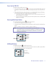
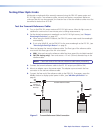
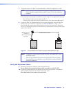
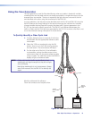
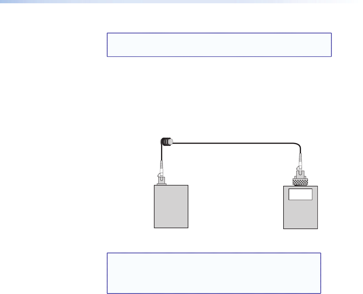
Transmit Reference Cable
MM: Mandrel Wrap
(shown), or
SM: 1.2 inch (30 mm)
Dia Loop
FLS 101
FPM 101
0 dB
Figure 8. Transmit Reference Cable Connection After Reference Set
NOTE: To display the stored reference power levels for each wavelength, press
the Ref/Set button.
When setting a reference level from multiple WAVE ID sources, allow a
few seconds for the wavelengths to be identified and measured before
storing the references.
Verify the Reference Cables:
9. Disconnect the transmit reference cable from the FPM 101.
Do not disturb the transmit reference cable connection on the FLS 101.
10. If necessary, change the FPM 101 adapter cap to match the connector of the receive
reference cable that will be connected to the power meter.
Clean both ends of the receive reference cable.