


Setup, cont’d
2-4
Refer also to the IPL 250 Reference Manual at www.extron.com.
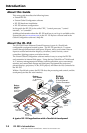
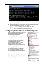
IPL 250 • Setup
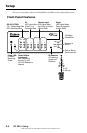
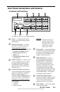
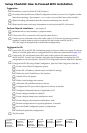
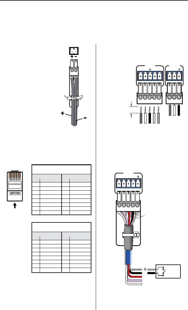
Power
Connectthe
Extron12VDC,
1.0A(max.)
powersupply
to
a
asshown
here:
N
You must
use the supplied
Extron external 12 V,
1.0 A power supply.
Control
Ethernet/LAN (
b
)
RJ-45
Connector
Insert Twisted
Pair Wires
Pins:
12345678
Straight-through Cable
(for connection to a switch, hub, or router)
End 1 End 2
Pin Wire Color Pin Wire Color
1 white-orange 1 white-orange
2 orange 2 orange
3 white-green 3 white-green
4 blue 4 blue
5 white-blue 5 white-blue
6 green 6 green
7 white-brown 7 white-brown
8 brown 8 brown
Crossover Cable
(for direct connection to a PC)
End 1 End 2
Pin Wire Color Pin Wire Color
1 white-orange 1 white-green
2 orange 2 green
3 white-green 3 white-orange
4 blue 4 blue
5 white-blue 5 white-blue
6 green 6 orange
7 white-brown 7 white-brown
8 brown 8 brown
Tie
Wrap
Ridges
Smooth
Wiring
C
Installation and service must be performed by authorized personnel only.
Attachcablesusingthefollowingwiringdiagramsasaguide.Fulldetailsare
availableintheIPL 250 Reference Manual.
Serial/RS-232 (
c
,
d
)
WiringforCOM3isthesameasfor
COM2.
COM1
TXRX
RTS CTS
COM 2
TXRX
Transmit (Tx)
Receive (Rx)
Ground (GND)
Transmit (Tx)
Receive (Rx)
Ground (GND)
Request to send (RTS)
Clear to send (CTS)
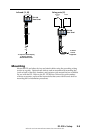
Strip wires
3/16”
(5 mm)
max.
Contact closure input (
g
)
INPUT
1234
IPL 250
Rear Panel
Switch,
Sensor
2
1
3
4
Heat Shrink
Over Shield