


Installation, cont’d
MPS Series • Installation2-4
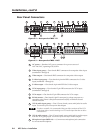
Rear Panel Connectors
50/60 Hz
100-240V 0.5A MAX
(VIDEO)
MPS 112
PROG OUT
OUT4321
OUT
OUT
OUT
RS-232
432
2
1
1
2
1
4
3
4
3
L
R
OUT4321
(S-VIDEO)
AUDIO
VIDEO VGA (VGA)
MIC IN
S-VIDEO
2 6 14 1693
5
7
8
11
10
4
1 15 17 18
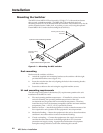
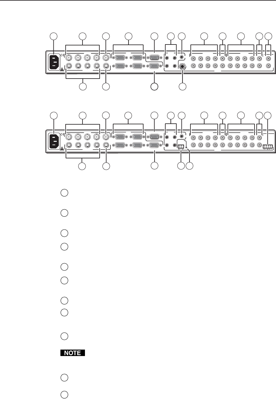
Figure 2-2 — Rear panel of MPS 112
50/60 Hz
100-240V 0.5A MAX
(VIDEO)
MPS 112CS
PROG OUT
OUT4321
OUT
OUT
OUT
RS-232
432
2
1
1
2
1
4
3
4
3
L
R
OUT4321
(S-VIDEO)
AUDIO
VIDEO VGA (VGA)
(S-VIDEO)
LR
PHANTOM
POWER
MIC IN
2
6
14
16
9
8
10 191 15 17
5
7
12
4
13
3
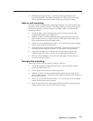
Figure 2-3 — Rear panel of MPS 112CS
1
AC power — Standard AC power connector for a power source of
100 – 240 VAC, operating at 50/60 Hz
2
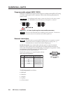
Video input group — Four female BNC connectors for composite video input
(numbered 1 through 4)
3
Video output — One female BNC connector for composite video output
4
S-video input group — Four female 4-pin mini DIN connectors for S-video
input (numbered 1 through 4)
5
S-video output — One female 4-pin mini DIN for S-video output
6
VGA input group — Four female 15-pin HD connectors for VGA input
(numbered 1 through 4)
7
VGA output — One female 15-pin HD connector for VGA output
8
RS-232 remote — One female 9-pin D connector for a host computer or a
controller using Extron’s Simple Instruction Set (SIS) or Windows-based
control software
9
(VGA) audio input group — Four 3.5 mm, female, stereo mini jacks for audio
input. See Audio input and output in this chapter.
To reduce crosstalk, it is recommended that you either terminate all the VGA
audio input jacks or avoid switching to a VGA audio input that has no device
connected to it.
10
(VGA) audio output — One 3.5 mm, female, stereo mini jack for audio output
from the VGA group input. See Audio input and output in this chapter.
11
Microphone input (MPS 112) — 6.3 mm mono microphone jack connection
for an external microphone