


2-5MPS Series • Installation
12
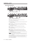
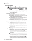
Microphone input (MPS 112CS) — A 3-pole, 3.5 mm captive screw connector
socket for an external microphone
13
Phantom Power LED (MPS 112CS) — A green LED that indicates (when lit)
that phantom power is on
14
(S-video) audio input group — Eight female RCA connectors (four right and
four left) for audio input (numbered 1 through 4)
15
(S-video) audio output — Two female RCA connectors (one right and one left)
for audio output from the S-video group inputs. See Audio input and output in
this chapter.
16
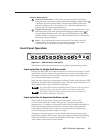
(Composite Video) audio input group — Eight female RCA connectors (four
right and four left) for audio input (numbered 1 through 4)
17
(Composite Video) audio output — Two female RCA connectors (one right
and one left) for audio output from the Video group inputs. See Audio input
and output in this chapter.
18
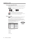
Program Audio output (MPS 112) — Two female RCA (one right and one left)
for program audio output (unbalanced)
19
Program Audio output (MPS 112CS) — A 3.5 mm, 5-pole captive screw
connector socket for balanced or unbalanced program audio output
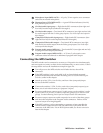
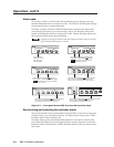
Connecting the MPS Switcher
The MPS switcher can be connected to as many as 12 input devices simultaneously
and can output to as many as three devices simultaneously, or one at a time. Follow
the steps below and see the installation example in figure 2-4.
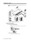
1
Turn off power to the MPS switcher and all other devices that will be
connected.
2
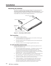
If the MPS switcher is to be rack, table/wall, or through-desk mounted,
position the brackets and insert the mounting screws. See the Mounting the
Switcher, earlier in this chapter.
3
Attach up to four VGA, four S-video, and four video (composite) input
devices to the MPS switcher.
4
Connect the switcher’s VGA, S-video, and video (composite) outputs (up to
three, one of each video format) to a projector’s inputs.
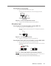
5
For stereo audio input, connect up to 12 audio sources to the switcher’s audio
inputs of the VGA, S-video, or video (composite) groups (up to four for each
group). See the following Audio input and output section for connections.
6
For stereo output, connect an audio output device to each of the three groups
and one audio amplifier to the Program Audio connectors. Refer to Audio
input and output for wiring diagrams.
7
If the MPS switcher is to be connected to a computer or host controller for
remote control, connect the host’s RS-232 cable to the 9-pin female RS-232
connector of the MPS unit. For an RS-232 pinout table, see Remote connection
later in this chapter.