


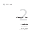
Installation, cont’d
MPS Series • Installation2-8
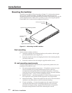
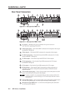
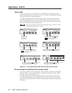
DB9 Pin Locations
Female
51
96
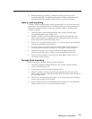
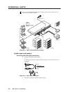
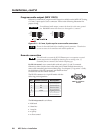
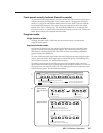
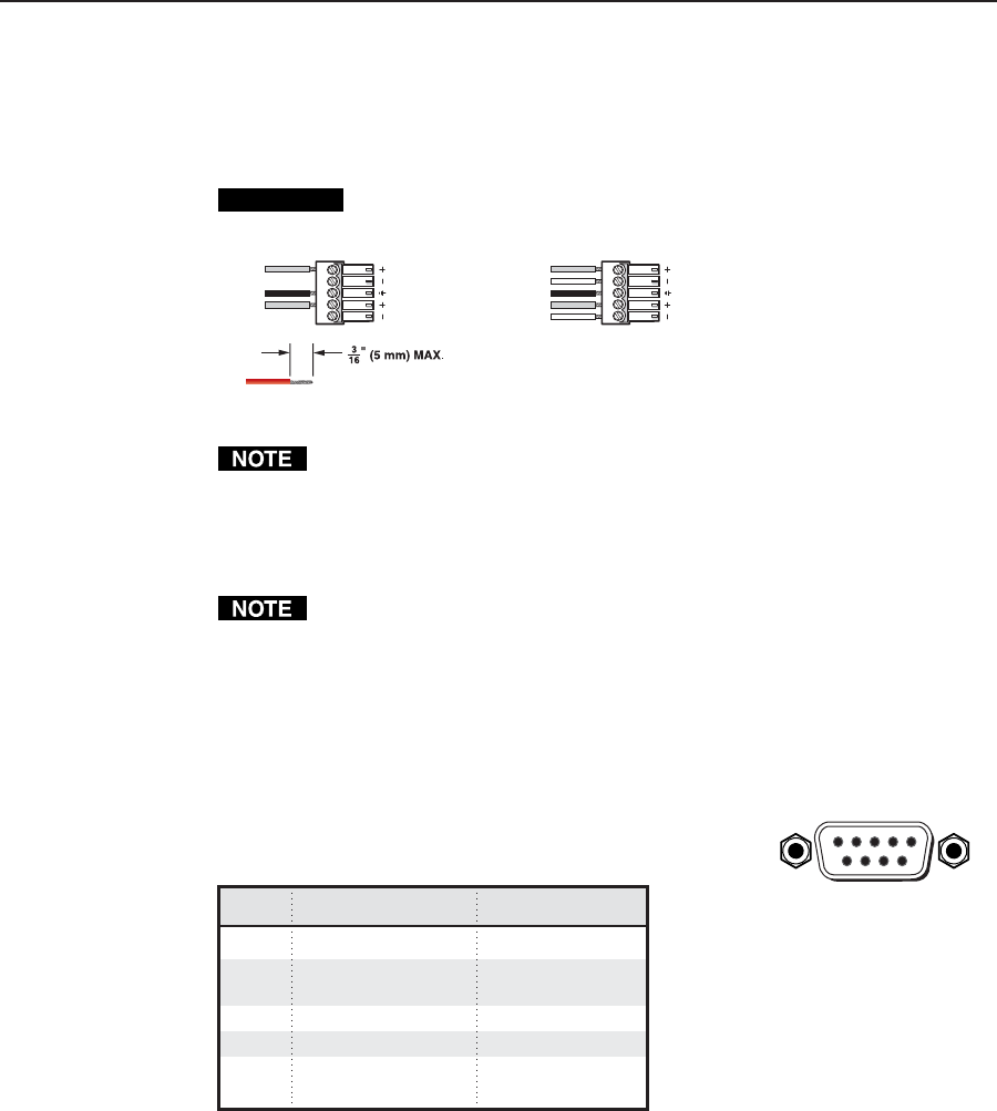
Program audio output (MPS 112CS)
Balanced or unbalanced program audio output is available on the MPS 112CS using
a 3.5 mm, 5-pole captive screw connector. Refer to the following illustration for
proper wiring.
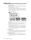
CAUTION
For unbalanced audio output, connect the sleeve(s) to the center ground
pin. DO NOT connect the sleeve(s) to the negative (-) contacts.
Tip
NO Ground Here
Sleeve(s)
Tip
NO Ground Here
Tip
Ring
Sleeve(s)
Tip
Ring
p p
LR
AUDIO
LR
AUDIO
Figure 2-9 — 3.5 mm, 5-pole captive screw audio connectors
Do not tin the audio leads before installing into the connector. Tinned wires
are not as secure in the connector and could be pulled out.
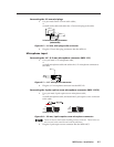
Remote connection
The cable used to connect the RS-232/Remote port to a computer or control
system may need to be modified by removing pins or cutting wires. If
unneeded pins are connected, the switcher may hang up.
For RS-232 control, use a control cable with only pins 2, 3, and 5 connected.
Otherwise, either cut the wires to the other pins in hard-shelled connectors or
remove the unneeded pins from molded plugs. See chapter 5, Programmer’s Guide,
for definitions of the SIS commands and details on how
to install and use the control software.
The RS-232 connector is a 9-pin D female with the
following pin designations:
Pin RS-232 function Description
1 – No connection
2 Tx Transmit data
3 Rx Receive data
4 – No connection
5 Gnd Signal ground
6, 7 – No connection
8, 9 – No connection
The RS-232 protocol is as follows:
• 9600 baud
• 8 data bits
• 1 stop bit
• no parity
• no flow control