


2-2
Refer also to the MPX Plus 866 A User’s Manual at www.extron.com. Refer also to the MPX Plus 866 A User’s Manual at www.extron.com.
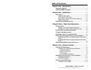
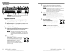
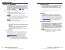
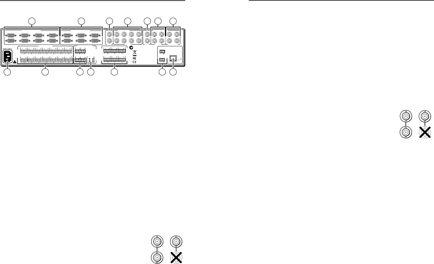
Rear Panel
COMPUTER INPUTS
VIDEO OUTPUT
O
U
T
P
U
T
S
O
U
T
P
U
T
S
1 23
6
45
I
N
P
U
T
S
12345
10
7
11
89
6
13
12
14
RESET
PHANTOM
+48V
15 16
17 18
LAN
ACT
LINK
9
10
11
C
12
Y/VID
C
Y/VID
C
C
Y
Y/VID
C
Y/VID
13 14 7
8
9 10 11 12
PASS -THROUGH
S-VIDEOS-VIDEO
VIDEOVIDEO
VIDEO INPUTS
AUDIO INPUTS
COMPUTER OUTPUTS
15
16
17
18
I
N
P
U
T
S
RS-232
PRIMARY
RS-232
SECONDARY
Tx Rx
Tx Rx
1357
2468
135
246
MIC/LINE INPUTS
N15779
1 2 53 74 6
1111
1314 108 9 11 12
C
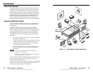
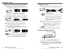
Turn off power to the input and output devices, and
disconnect their power cords.
Computer video group
a
RGB video inputs — Connect the analog computer-video
sources to the Computer Input 1 through Computer Input 8
15-pin HD female connectors.
b
RGB video outputs — Connect RGBHV video displays to the
Computer Output 1 through Computer Output 6 15-pin HD
female connectors.
Low resolution video group
c
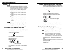
Video Input 9 and Video Input 10 (composite video inputs) —
Connect composite video sources to these female BNC
connectors.
N
Video Input 9 serves as a timing reference for all other
low resolution video group inputs. If one of the inputs is
synced to a blackburst generator, connect that source to
Input 9.
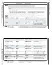
d
Input 11 through Input 14 —
S-video inputs — Connect an S-video source
to a pair of female BNC connectors. Connect
luma (Y) and chroma (C) as shown at right.
Composite video inputs — Connect a
composite video source to the Video (top)
connector in a pair of female BNC connectors
as shown at right.
e
Composite video outputs (Output 7 and Output 8) —
Connect composite video displays to these female BNC
connectors.
N
If the input tied to Output 7 or Output 8 is S-video, the
switcher encodes the input to composite video.
If the tied input is composite video, the switcher passes it
through to the output with no processing.
f
S-video outputs (Output 9 and Output 10) —
Connect S-video displays to these female BNC connectors.
N
If the input tied to Output 9 or Output 10 is composite
video, the switcher decodes the input to S-video.
If the tied input is S-video, the switcher passes it through
to the output with no processing.
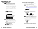
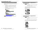
g
Pass-through outputs
(Output 11 and Output 12) —
Connect S-video or composite video displays
to these female BNC connectors. Connect
S-video Y and C or composite video as shown
at right.
N
The switcher passes the tied input to
these outputs with no signal processing; an S-video input
is output as S-video, a composite video input is output as
composite video.
12
Y/VID
S-video Composite
video
C
11
12
Y/VID
S-video Composite
video
C
11
MPX Plus 866 A • Installation
Installation
MPX Plus 866 A • Installation
2-3