


Refer also to the MPX Plus 866 A User’s Manual at www.extron.com.
Refer also to the MPX Plus 866 A User’s Manual at www.extron.com.
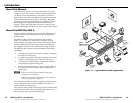
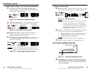
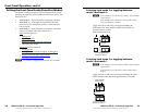
Audio inputs, outputs, and mic power indicators
h
Connections for balanced and unbalanced audio inputs —
Connect balanced or unbalanced
stereo audio inputs to these
5-pole captive screw connectors.
L R
Unbalanced Input
Balanced Input
Ring
Sleeve (s)
Tip
Sleeve
Tip
Sleeve
Tip
Tip
Ring
Do not tin the wires!
Figure 2-4 — Audio input connector wiring
i
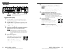
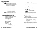
Mic/line level audio inputs — Connect balanced or unbalanced
mono audio inputs to these 3-pole captive screw connectors.
Do not tin the wires!
Balanced mono
Unbalanced mono
Jumper
Tip (+)
Gnd (Sleeve, )
Tip (+)
Ring (–)
Gnd (Sleeve, )
Figure 2-5 — Mic input connector wiring
j
Phantom +48 V LEDs — These four LEDs, numbered 15
through 18, light to indicate that +48 V phantom power is
applied to the associated mic/line inputs.
k
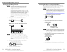
Local audio outputs (most audio models) — Connect balanced
or unbalanced stereo audio output devices to these 5-pole
captive screw connectors.
CAUTION Connect the sleeve to ground. Connecting the sleeve to a
negative (-) terminal will damage the audio output circuits.
Unbalanced Output
Balanced Output
L R
Ring
Tip
Sleeve(s)
Tip
Ring
Sleeve(s)
Tip
Tip
NO GROUND
NO GROUND
Do not tin the wires!
Figure 2-5 — Audio output connector wiring
Remote control ports
l
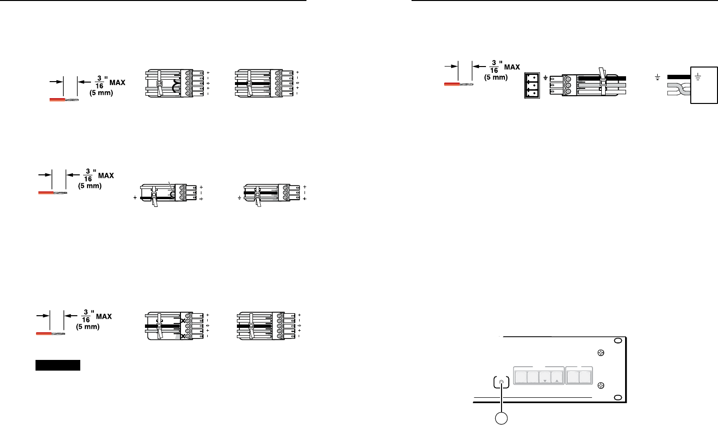
RS-232 connectors — Connect one or two host devices to these
3-pole captive screw connectors for serial RS-232 (gure 2-7).
Rx
Tx
PC
Ground ( )
Receive (Rx)
Transmit (Tx)
Rx
Tx
Bidirectional
Do not tin the wires!
Figure 2-7 — RS-232 connector
N
The two rear panel ports are hardwired for RS-232 only.
The RS-232 Secondary port is active only if the front
panel Configuration port is not in use. If a front panel
configuration connection is made, the rear panel RS-232
Secondary port becomes inactive and the front panel
Configuration port is active.
m
LAN port — If desired, connect a network WAN or LAN hub, a
control system, or computer to the Ethernet RJ-45 port.
Network connection• — Wire as a patch (straight) cable.
Computer or control system connection• — Wire the
interface cable as a crossover cable.
N
The factory default IP address is 192.168.254.254.
n
Power — Plug the switcher into a grounded AC source.
Front Panel Configuration Port
AUDIO
VIDEO
I/O
CONTROL
ENTER PRESET
VIEW
ESC
PRESENTATION MATRIX SWITCHER
MPX PLUS 866 A
CONFIG
15
Figure 2-7 — Front panel configuration port
o
Configuration port — If desired, connect a control system
or computer to the front panel Conguration (RS-232) port.
Use an optional 9-pin D to 2.5 mm mini jack TRS RS-232
cable, part #70-335-01.
MPX Plus 866 A • Installation
Installation, cont’d
2-4
MPX Plus 866 A • Installation
2-5