


Refer also to the VersaTools
®
MTP Series User’s Manual at www.extron.com.
c
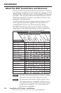
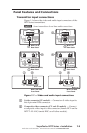
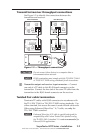
Audio input captive screw connector (MTP T SV A,
MTP T AV) — Connect a balanced or unbalanced audio input
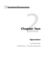
to this 3.5 mm, 5‑pole captive screw connector. Connectors are
included with each MTP. See Figure 1‑2 to wire a connector
for the appropriate input type. Use the supplied tie‑wrap to
strap the audio cable to the extended tail of the connector. High
impedance is generally over 800 ohms.
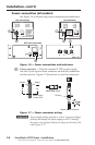
L R
L R
Unbalanced Stereo Input
Balanced Stereo Input
(high impedance)
(high impedance)
Do not tin the wires!
Ring
Sleeve (s)
Tip
Sleeve
Tip
Sleeve
Tip
Tip
Ring
Figure 1-2 — Captive screw input connector wiring
C
The length of exposed wires is critical. Ideal length is
3/16” (5 mm). If the stripped section of wire is longer
than 3/16”, the exposed wires may touch, causing a short
circuit. If the stripped section of wire is shorter, wires can
easily be pulled out even if tightly fastened by the captive
screws.
N
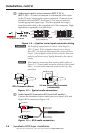
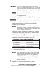
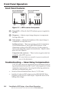
When making connections from existing audio cables see
Figure 1-3. A mono audio connector consists of the tip and
sleeve. A stereo audio connector consists of the tip, ring,
and sleeve.
Tip (+)
Sleeve ( )
RCA Connector (Mono)
Sleeve ( )
Ring (R)
Tip (L)
3.5 mm Stereo Plug Connector
(unbalanced)
Figure 1-3 — Typical audio connectors
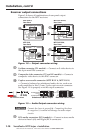
d
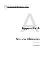
Audio input RCA connectors (RCA and AAP models) —
Connect an unbalanced stereo audio source to these L(eft) and
R(ight) RCA connectors (Figure 1‑4).
Sleeve (Gnd )
Right Channel
(Red Jacket)
Left Channel
(White Jacket)
Tip (Signal)
Figure 1-4 — RCA audio connectors
VersaTools
®
MTP Series • Installation
Installation, cont’d
1-6