


Refer also to the VersaTools
®
MTP Series User’s Manual at www.extron.com.
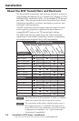
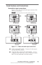
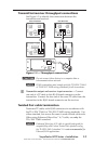
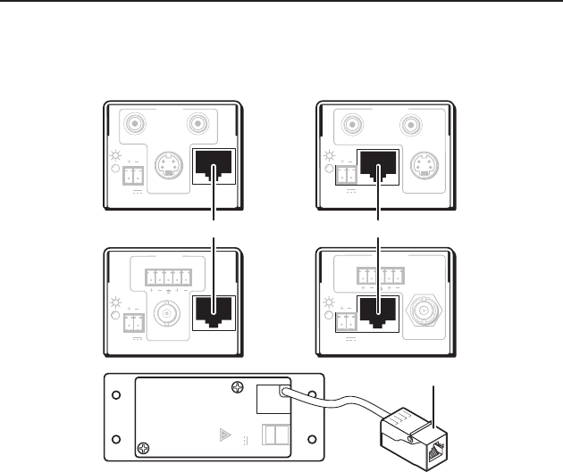
Transmitter/receiver throughput connections
See Figure 1‑5 to identify the connections between the
transmitter and receiver.
12V
0.5A MAX
OUTPUT
POWER
− +
MTP Transmitters MTP Receivers
INPUT
LR
MTP T AV
OUTPUT
VIDEO
12V
0.5a
INPUT
MTP T SV A RCA
OUTPUT
MAX
12V
0.5a MAX
S-VIDEO
LR
OUTPUT
MTP R SV A RCA
INPUT
S-VIDEO
12V
0.5a MAX
OUTPUT
MTP R AV
LR
INPUT
VIDEO
12V
0.5a MAX
R
L
e
e
e
Figure 1-5 — Throughput connections
C
Do not connect these devices to a computer data or
telecommunications network.
N
RJ-45 termination must comply with the TIA/EIA T 568A
or TIA/EIA T 568B wiring standards for all connections.
e
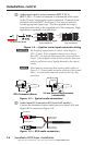
Transmitter output and receiver input connector — Connect
one end of a TP cable to this RJ‑45 female connector on the
transmitter. Connect the free end of the same TP cable from the
transmitter to the RJ‑45 female connector on the receiver.
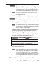
Twisted Pair cable termination
Terminate TP cables with RJ‑45 connectors in accordance with
the TIA/EIA T 568A or TIA/EIA T 568B wiring standards. Use
either standard, but ensure the same is used on both cable ends.
When using Enhanced Skew‑Free
™
A/V cable, use only the
TIA/EIA T 568A standard.
N
Enhanced Skew-free A/V cable is specially designed for
compatibility with Extron Twisted Pair products using
the TIA/EIA 568 A standard. It is not recommended for
Ethernet/LAN applications.
VersaTools
®
MTP Series • Installation
1-7