


2-2
Refer also to the VersaTools
®
MTP Series User’s Manual at www.extron.com.
Front Panel Features
SHARP
C GAIN
Y GAIN
SHARP
GAIN
MTP R S-video Receiver
Front Panel
MTP R Composite Video
Receiver Front Panel
aabbccc
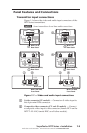
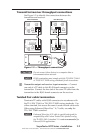
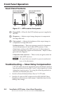
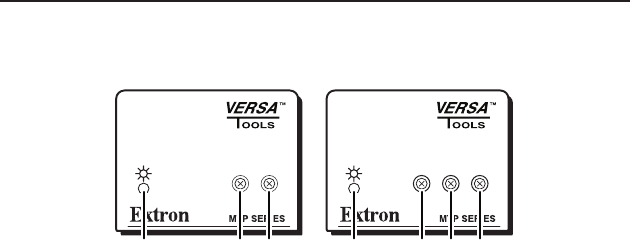
Figure 2-1 — MTP receiver front panels
a
Power LED — When lit, this LED indicates power is applied to
the MTP.
b
Sharpness — Adjusts output image sharpness to compensate
for long cable runs.
c
Gain control — Adjusts the brightness of the output image to
compensate for long cable runs.
S-video receivers — There are separate controls for luminance
(Y) and chrominance (C) on S‑video MTP receivers. If the
chrominance setting on the MTP receiver’s S‑video output is
too low, the image may appear in monochrome. Adjust S‑video
gain until color appears.
Composite video receivers — There is only one gain control on
composite video MTP receivers.
N
All control knobs are removable to prevent unauthorized
access to the adjustments.
Troubleshooting — Skew Delay Compensation
CAT 5 TP cable can cause registration errors (luminance leads or
lags chrominance) between the Y and C video signals on S‑video
transmitter/receiver pairs. Try using the following methods to
minimize or eliminate pair skew:
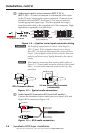
Switch to Extron Enhanced Skew‑Free A/V UTP cable.•
Install an S‑video‑to‑BNC adapter and an SEQ 100 BNC Skew •
Equalizer on the receiver video output. Adjust the skew for the
leading video image.
VersaTools
®
MTP Series • Front Panel Operation
Front Panel Operation