


Refer also to the VersaTools
®
MTP Series User’s Manual at www.extron.com.
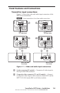
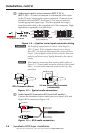
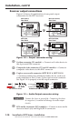
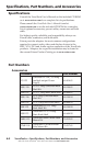
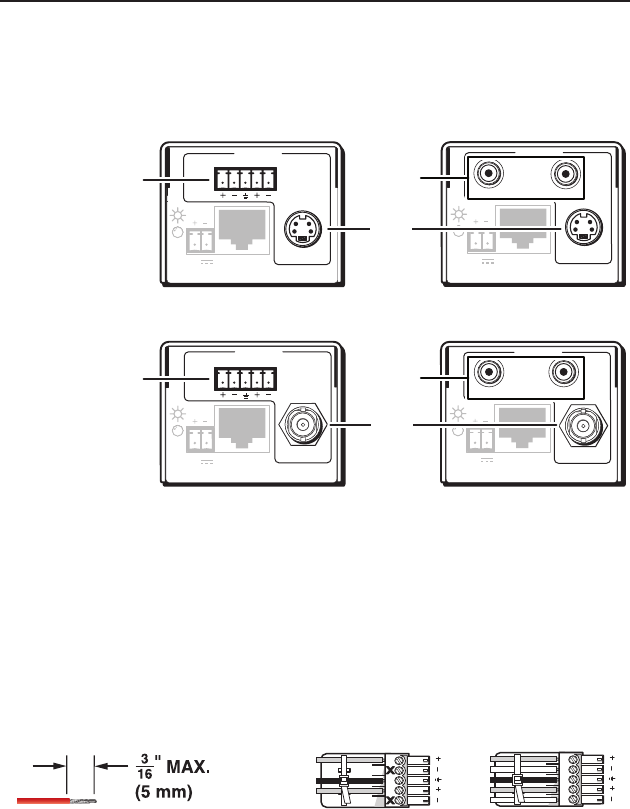
Receiver output connections
Figure 1‑8 shows all combinations of rear panel output
connections for the MTP receivers.
MTP R AV RCA,
Rear Panel
MTP R AV,
Rear Panel
MTP R SV A RCA,
Rear Panel
MTP R SV A,
Rear Panel
OUTPUT
MTP R AV RCA
INPUT
VIDEO
12V
0.5a MAX
LR
OUTPUT
MTP R SV A
L R
INPUT
S-VIDEO
12V
0.5a MAX
OUTPUT
MTP R SV A RCA
INPUT
S-VIDEO
12V
0.5a MAX
L
R
OUTPUT
MTP R AV
LR
INPUT
VIDEO
12V
0.5a MAX
j
j
k
k
i
h
Figure 1-8 — Output connector wiring
h
S-video connector (SV models) — Connect an S‑video device to
this 4‑pin mini DIN connector.
i
Composite video connector (CV and AV models) — Connect a
composite video device to this BNC connector.
j
Captive screw audio connector (MTP R SV A, MTP R AV)
— Connect a balanced or unbalanced audio device, such as an
audio amplier, to this 3.5 mm, 5‑pole captive screw connector.
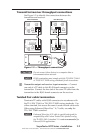
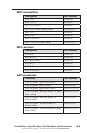
See Figure 1‑9 to properly wire the output connector.
Unbalanced Stereo Output Balanced Stereo Output
L R
Do not tin the wires!
Ring
Sleeve(s)
Tip
Tip
Ring
Sleeve(s)
Tip
Tip
NO GROUND HERE.
NO GROUND HERE.
Figure 1-9 — Audio Output connector wiring
C
Connect the sleeve to ground (_). Connecting the sleeve
to a negative (-) terminal will damage the audio output
circuits.
k
RCA audio connectors (RCA models) — Connect a stereo audio
device to these L(eft) and R(ight) RCA connectors.
VersaTools
®
MTP Series • Installation
Installation, cont’d
1-10