


Refer also to the VersaTools
®
MTP Series User’s Manual at www.extron.com.
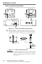
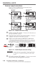
Power connection (all models)
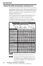
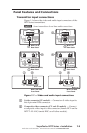
See Figure 1‑6 to identify the power connections and indicators.
INPUT
MTP T SV A RCA
OUTPUT
S-VIDEO
LR
12V
0.5a
MAX
OUTPUT
MTP R SV A RCA
INPUT
S-VIDEO
R
L
12V
0.5a MAX
AUDIO IN
VIDEO
IN
LR
MTP T AV
12V
0.5A MAX
OUTPUT
POWER
− +
MTP AAP Transmitters
MTP Transmitters MTP Receivers
gg
fg
f
f
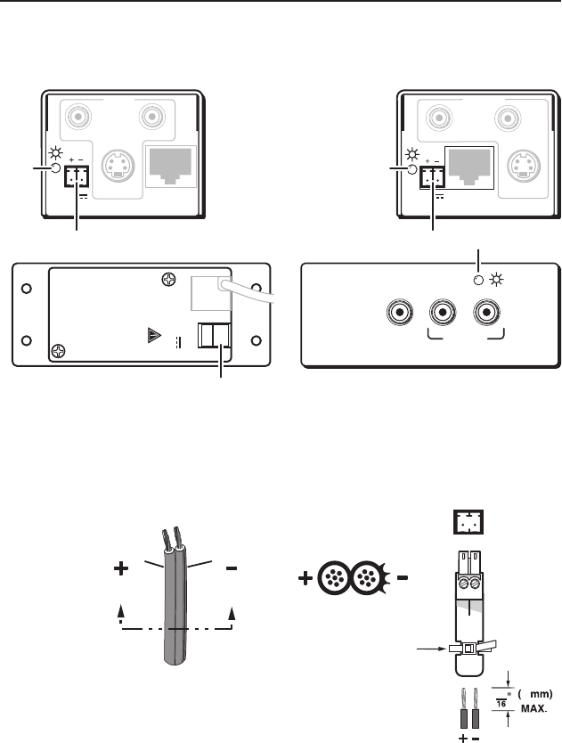
Figure 1-6 — Power connections and indicators
f
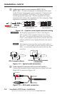
Power connector — Plug the external 12 VDC power supply
into this 2‑pole captive screw connector on both the transmitter
and the receiver. Figure 1‑7 shows how to wire the connectors.
Captive Screw Connector
SECTION A–A
Power Supply
Output Cord
Ridges
A
Smooth
A
Tie Wrap
+ _
3
5
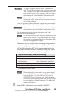
Figure 1-7 — Power connector wiring
C
Power supply voltage polarity is critical. Incorrect voltage
polarity can damage the power supply or MTP. Identify
the power cord negative lead by the ridges on the side of the
cord (Figure 1-7).
VersaTools
®
MTP Series • Installation
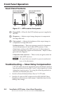
Installation, cont’d
1-8