


Refer also to the MTPX Plus User’s Manual at www.extron.com.
Refer also to the MTPX Plus User’s Manual at www.extron.com.
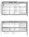
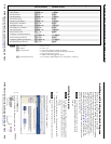
Command ASCII command
(host to switcher)
Response
(switcher to host)
Additional description
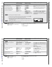
Input signal level and peaking and auto calibrate
Set input signal level
EX!
*
X^
Ipek
}
Ipek
X!
*
X^]
Set a specific pre-peak level for the TP
input.
Increment input peaking
EX!
+Ipek
}
Ipek
X!
*
X^]
Increase the input pre-peaking level by 1.
Decrement input peaking
EX!
-Ipek
}
Ipek
X!
*
X^]
Decrease the pre-peaking level by 1.
Read input peaking setting
EX!
Ipek
} X^]
Execute auto calibration
EX!
*0AADJ
}
Aadj
X!
*2
]
{start}
Qik
]
{tie creation}
Aadj
X!
*
X&]
{finished}
Ipek
X!
*
X^]
{new value}
Tie input
X!
to output 1 and auto adjust
the peaking on input
X!
. The
X&
value
in the response reports whether the
adjustment value was within or outside of
the threshold.
N
Before issuing the auto calibration command:
1
. Disconnect the power and RJ-45 cables at the MTP transmitter connected to
X!
.
2
. Connect the two cables to the included MTP signal generator.
3
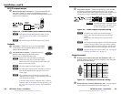
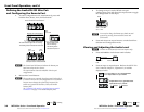
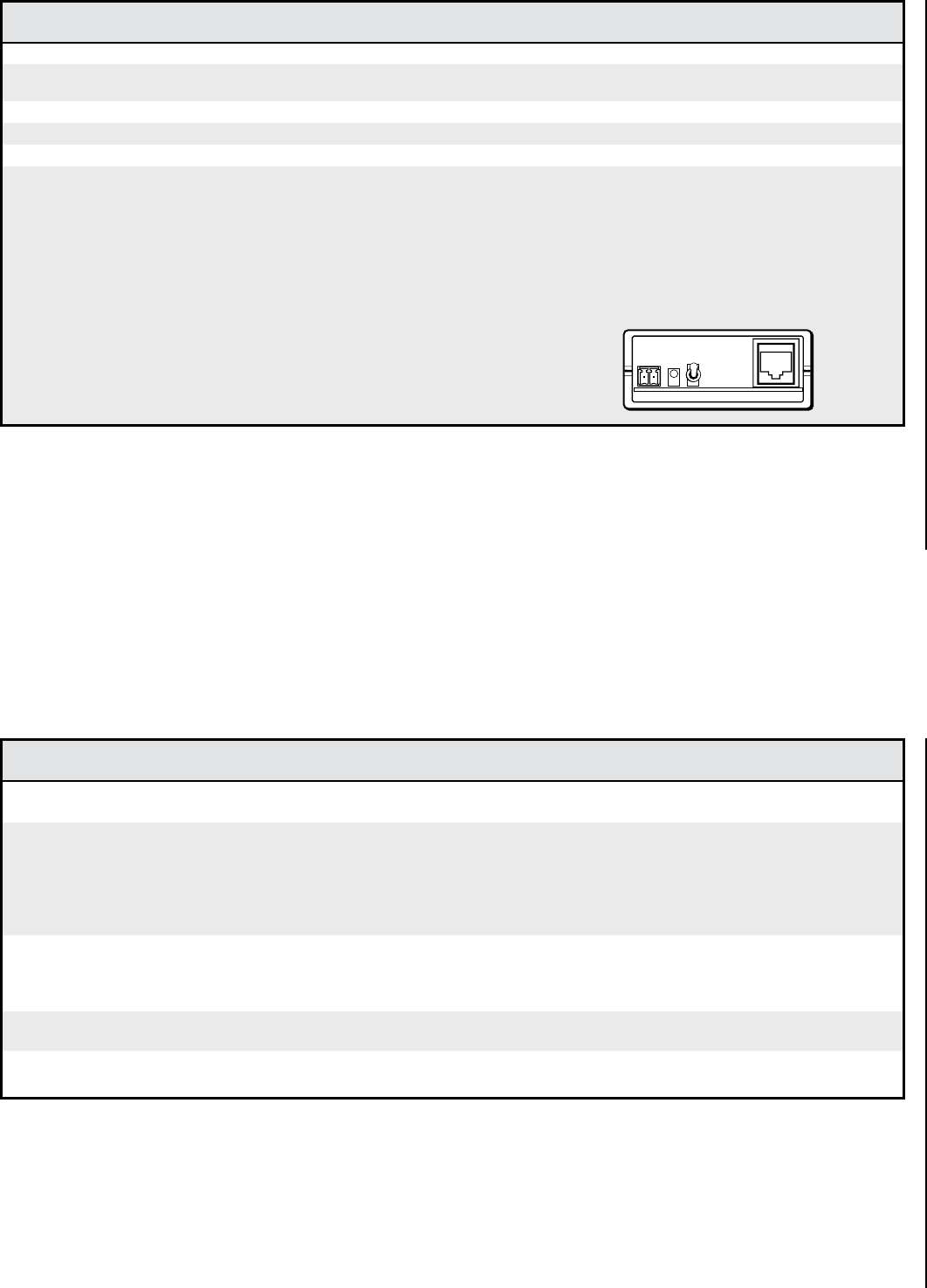
. If the input cable is longer than 300 feet (90 m), place the Pre-Peak switch on the
MTP signal generator to on (up when the signal generator‘s RJ-45 connector is to the
right as shown at right).
N
The MTP signal generator does not work on cable lengths over 400 feet (120 m). Set the
level and peaking to its maximum value of 255.
Pre-Peak
is on.
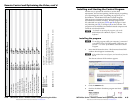
Command ASCII command
(host to switcher)
Response
(switcher to host)
Additional description
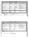
Input skew adjustment
N
For the MTPX Plus, these commands apply to inputs 5 through 12 only.
Set all input skew adjustment
values
EX!
*
X*
*
X*
*
X*
Iseq
}
Iseq
X!
*
X*
*
X*
*
X*]
Set a specific skew adjustment for the TP
input.
X*
values are listed in RGB order.
Example:
E
2*0*0*4Iseq
}
Iseq02*0*0*4
]
Set the skew settings for input 2 as follows:
Red = 0 ns
Green = 0 ns
Blue = 8 ns (delayed 8 ns)
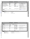
Increment one input skew
adjustment value
EX!
*
X(
+Iseq
}
Iseq
X!
*
X*
*
X*
*
X*]
Increase the
X(
skew plane adjustment for
input
X!
by 1 step (2 ns).
Example:
E
2*2*+Iseq
}
Iseq02*0*0*5
]
Increase the blue skew input for 2 by 2 ns
(from 8 ns to 10 ns).
Decrement one input skew
adjustment value
EX!
*
X(
-Iseq
}
Iseq
X!
*
X*
*
X*
*
X*]
Decrease the
X(
skew plane adjustment for
input
X!
by 1 step (2 ns).
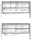
Read input skew adjustment
values
EX!
Iseq
} X*
*
X*
*
X*]
N
X!
= Input number
01 – (maximum number of inputs for your model)
X^
= Input signal level/peaking range 000 – 255
X&
= Threshold 0 = outside of threshold
1 = within threshold
N
X!
= Input number
01 – (maximum number of TP inputs for your model)
X*
= Skew adjustment range 00 – 31 (each step = 2 ns)
X(
= Video plane 0 = red
1 = green
2 = blue
MTPX Plus Series • Remote Control and Optimizing the Video
Remote Control and Optimizing the Video, cont’d
4-6
MTPX Plus Series • Remote Control and Optimizing the Video
4-7