


Refer also to the MTPX Plus User’s Manual at www.extron.com.
Refer also to the MTPX Plus User’s Manual at www.extron.com.
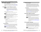
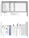
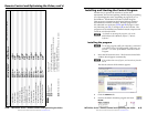
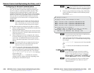
2. Choose the comm (serial) port that is connected to the
switcher or IP [LAN].
N
For a comm port, check the baud
rate displayed in the window. If you
need to change the baud rate, click the
Baud button and double-click the
desired baud rate.
3. Click OK.
If you selected a serial port in step 2, the Matrix Switchers
Control Program is ready for operation.
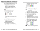
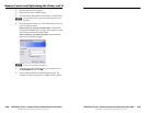
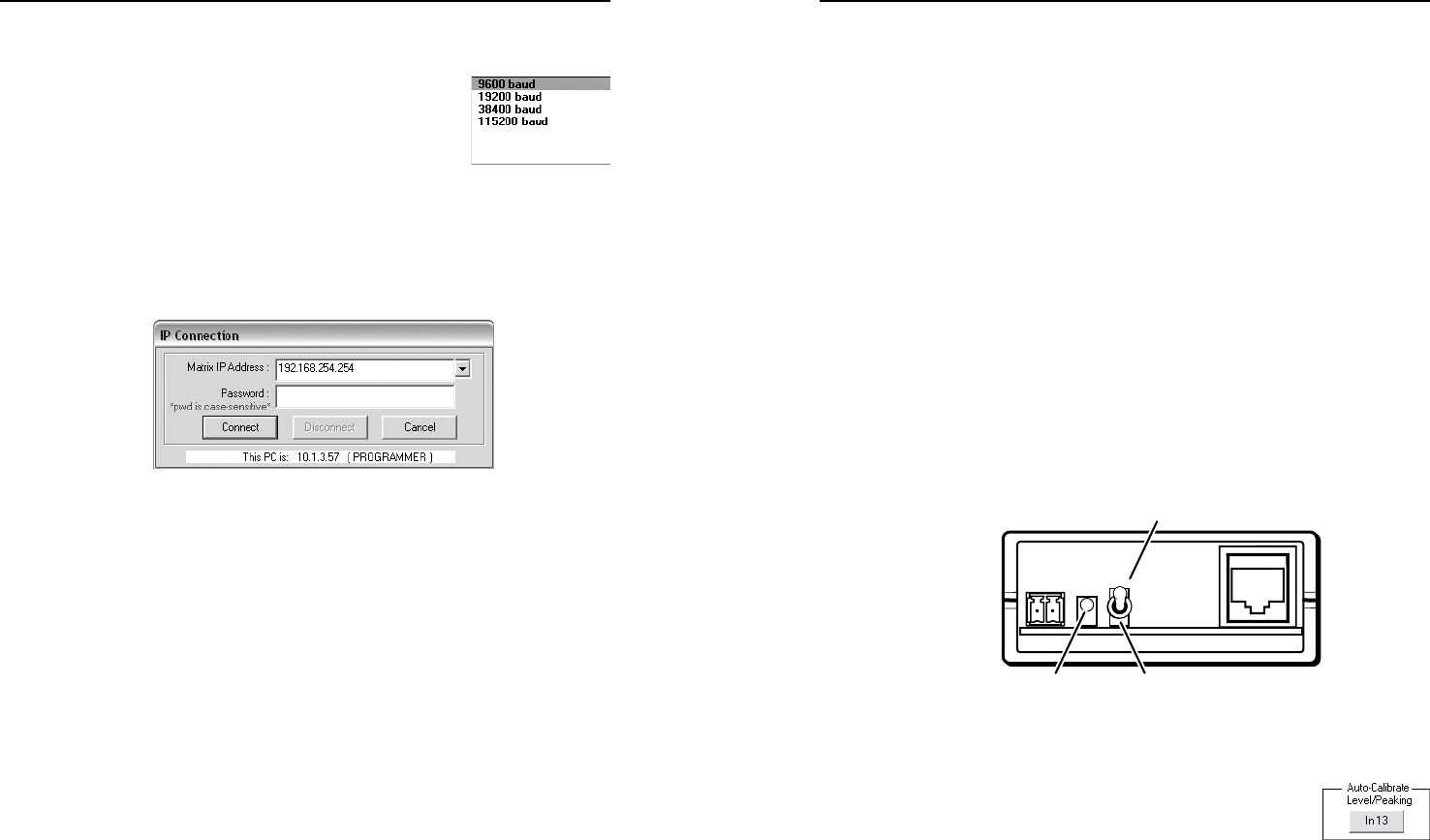
If you selected IP [LAN] in step 2, the IP Connection
window appears.
a. Examine the Matrix IP Address field, which displays
the last Matrix IP address entered.
If necessary, enter the correct IP address in the field.
N
192.168.254.254 is the factory-specified default value for
this field.
b. If the switcher is password protected, enter the
administrator or user password in the Password field.
c. Click Connect. The Matrix Switchers Control Program
is ready for operation.
Optimizing the video
Each TP input has a level and peaking adjustment. Most MTP
transmitters and half of the MTPX Plus TP outputs have a pre-
peaking feature. TP inputs and outputs have skew adjustments.
See the following sections to set these adjustable features.
N
Unless the TP cables are changed, these adjustments
should need to be made only once, during installation.
Before you start optimizing, set all input level and peaking,
input and output skew, and output pre-peak settings to either
zero or off.
Setting the MTP transmitter Pre-Peak feature
For inputs from MTP T 15HD products only — If the cable
between the MTP transmitter and the MTPX Plus is 300 feet
(91 m) or longer, turn on the Pre-Peak switch on the transmitter.
For shorter cables, turn the switch off.
Setting MTPX level and peaking using the MTP signal
generator
The simplest and surest way to set the input level and peaking
is to use the included MTP signal generator and the Auto-
calibration utility within the Matrix Switchers Control Program
as follows:
N
To manually set the input level and peaking, see
"Manually setting the MTPX level and peaking".
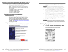
1. Disconnect the power and RJ-45 cables at the MTP transmitter
that is connected to the MTPX Plus input to be adjusted.
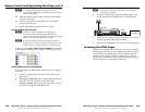
2. Connect the two cables to the included MTP signal
generator.
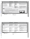
3. If the input cable between the transmitter and the MTPX
Plus is longer than 300 feet (91 m), place the Pre-Peak
switch on the MTP signal generator on (up).
Pre-Peak on (up) (shown)
Pre-Peak off (down)Power LED
N
The MTP signal generator does not work on cable lengths
over 400 feet (120 m). Set the level and peaking to their
maximum value of 255.
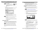
4. In the Matrix Switchers Control Program,
click Tools > MTPX Picture settings and
then click the Auto-Calibrate Level/
Peaking button.
After a few moments, the program reports whether or not
the calibration succeeded and the original and new settings
for the input level/peaking adjustment.
5. Disconnect the power and RJ-45 cables from the MTP
signal generator and reconnect them to the MTP
transmitter.
6. Repeat steps 1 through 5 for each MTPX Plus input.
MTPX Plus Series • Remote Control and Optimizing the Video
Remote Control and Optimizing the Video, cont’d
4-18
MTPX Plus Series • Remote Control and Optimizing the Video
4-19