


Refer also to the MTPX Plus User’s Manual at www.extron.com.
Refer also to the MTPX Plus User’s Manual at www.extron.com.
N
A 2-nanosecond adjustment is very fine. Up to 10
nanoseconds of delay may be necessary before you detect a
change in the display.
14. Adjust the leftmost video signal to the right until all three
colors are converged.
15. If either of the two the remaining colors is left shifted,
repeat steps 12 and 14.
16. Repeat steps 10 through 15 for all other outputs.
Selecting MTPX Plus Pre-Peak
N
MTPX Pre-Peak is available on all outputs of an
MTPX Plus 128 and the first half of MTPX Plus
outputs of the remaining MTPX Plus models (for example,
outputs 1 through 4 for an MTPX Plus 168).
N
If the cable between the MTPX Plus and the receiver is
300 feet (91 m) or longer, turn the Pre-Peak feature on the
MTPX Plus on. For shorter cables, turn the feature off.
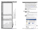
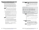
If necessary, click Tools > MTPX Picture settings and then click
in the output Pre-Peaking box to toggle Pre-Peaking on and off.
Setting MTP Receiver level/peaking
If level/peaking is available on the connected receiver, adjust it
as follows:
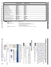
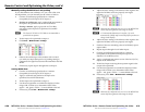
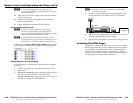
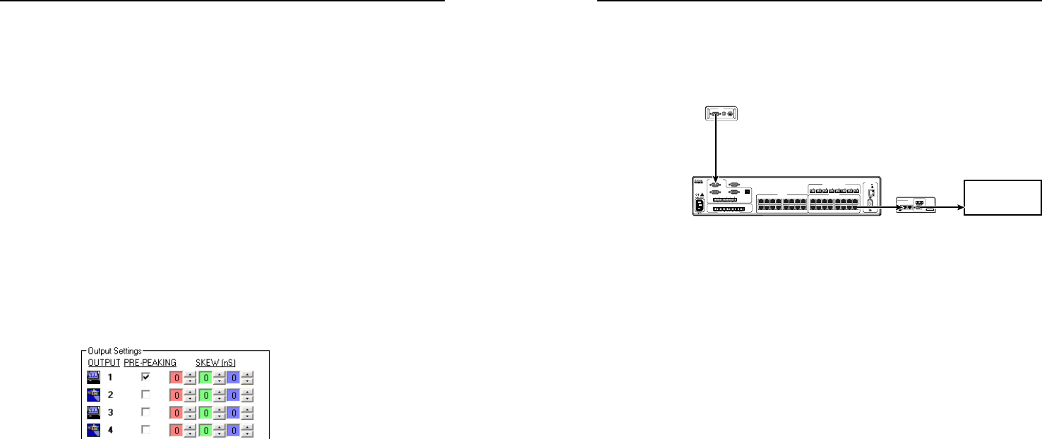
1. Connect an oscilloscope or monitor to the output of the
MTP receiver.
2. If using an oscilloscope, apply a white field test pattern to
one of the local (VGA) inputs on the MTPX Plus.
If using a monitor, apply a grayscale test pattern to one of
the local (VGA) inputs on the MTPX Plus.
H
The Extron VTG 300 or VTG 400 are recommended to
provide the test pattern.
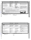
3. Tie the local input receiving the test pattern signal to the
output connected to the MTP receiver to be optimized.
MTP
Receiver
VTG 300
Local (VGA)
Input
MTPX Plus
INPUT
BUFFERED
OUTPUT
OUTPUT
POWER
12V
.5A MAX
MTP RL 15 HD A
ON
1 2 3 4 5 6
H SYNC +
V SYNC +
C SYNC
SOG
VIDEO
END UNIT
1
MONO AUDIO
2
MONO AUDIO OUTPUTS
OUT PU TS
RGB
RGB
1
2
3
1
Tx Rx
1
L
R
1 2
AUDIO
3
2
L
R
3
L
R
4
L
R
LOCAL INPUTS
LOCAL OUTPUT
RGB
RGB
INPUT SELECT
ON
LOCAL
RJ - 45
123
RS-232/RS-422
REMOTE
CONTROL
RS - 232 OUTPUT INSERT
Tx Rx
Tx Rx
Tx Rx
Tx Rx
Tx Rx
Tx Rx
Tx Rx
INPUTS
1 2 3 4 5 6 7 8
9 10 11 12 13 14 15 16
1 2 3 4 5 6 7 8
9 10 11 12 13 14 15 16
1 2 3 4 5 6 7 8
LAN
RESET
Oscilloscope
or display
RGB/R-Y,Y,B-Y S-VIDEOCOMPOSITE
VIDEO
4. Adjust the level and peaking on the receiver in accordance
with the applicable MTP product manual.
5. Repeat steps 1 through 4 for each receiver to be optimized.
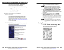
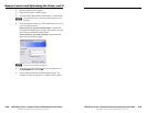
Accessing the HTML Pages
Another way to operate the switcher is via its factory-installed
HTML pages, which are always available and cannot be erased
or overwritten. The HTML pages are accessible through the
LAN port of the switcher when it is connected via a LAN or
WAN, using a web browser such as Microsoft Internet Explorer.
See
k
on page 2-6 for connection information.
MTPX Plus Series • Remote Control and Optimizing the Video
Remote Control and Optimizing the Video, cont’d
4-22
MTPX Plus Series • Remote Control and Optimizing the Video
4-23