


2-2
Refer also to the MTPX Plus User’s Manual at www.extron.com.
Refer also to the MTPX Plus User’s Manual at www.extron.com.
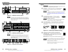
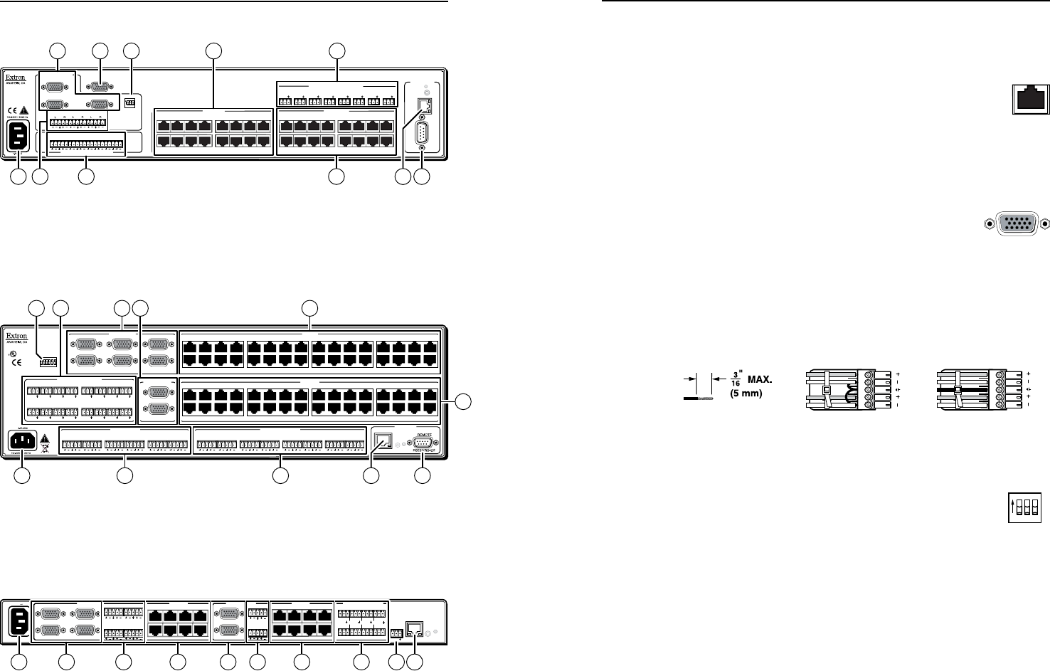
Rear Panel
MONO AUDIO OUTPUTS
OUTPUTS
RGB
RGB
1
2
3
1
Tx Rx
1
L
R
1 2
AUDIO
3
2
L
R
3
L
R
4
L
R
LOCAL INPUTS
LOCAL OUTPUT
RGB
RGB
INPUT SELECT
ON
LOCAL
RJ - 45
1 23
RS-232/RS-422
REMOTE
CONTROL
RS - 232 OUTPUT INSERT
Tx Rx
Tx Rx
Tx Rx
Tx Rx
Tx Rx
Tx Rx
Tx Rx
INPUTS
1 2 3 4 5 6 7 8
9 10 11 12 13 14 15 16
1 2 3 4 5 6 7 8
9 10 11 12 13 14 15 16
1 2 3 4 5 6 7 8
LAN
RESET
12 9
2 5
6
1
11
OUTPUTS
INPUTS
7 4
83
AUDIO
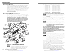
Figure 2-1 — MTPX Plus 1616 rear panel
N
The MTPX Plus 816 and MTPX Plus 168 are housed in
the same 2U enclosure as the MTPX Plus 1616, but have
fewer TP input or output connectors to accommodate their
smaller matrix sizes.
ETHERNET
ACT
INPUT
SELECT
LOCAL
RJ-45
LOCAL INPUTS
1 2 3 4 5 6 7 8 9 10 11 12 13 14 15 16
17 18 19 20 21 22 23 24 25 26 27 28 29 30 31 32
1 2 3 4 5 6 7 8 9 10 11 12 13 14 15 16
17 18 19 20 21 22 23 24 25 26 27 28 29 30 31 32
1
2
21 3
4 5 6
RS-232 OUTPUT INSERTION
LOCAL OUTPUTS OUTPUTS
INPUTS
CONTROLCONTROL
MONO AUDIO OUTPUTSAUDIO INPUTS
LINK
RESET
L R
1
L R
2
L R
3
L R
4
L R
5
L R
6
L R
1
L R
2
L R
3
L R
4
L R
5
L R
6
L R
7
L R
8
Tx Rx
1
Tx Rx
2
Tx Rx
3
Tx Rx
4
Tx Rx
5
Tx Rx
6
Tx Rx
7
Tx Rx
8
Tx Rx
9
Tx Rx
10
Tx Rx
11
Tx Rx
12
Tx Rx
13
Tx Rx
14
Tx Rx
15
Tx Rx
16
US
LIST ED
1T2 3
I.T.E .
®
6
12 911
4
83
125 7
LOCAL INPUTS
INPUTS
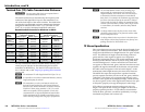
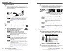
Figure 2-2 — MTPX Plus 3232 rear panel
N
The MTPX Plus 1632 and MTPX Plus 3216 are housed
in the same 3U enclosure as the MTPX 3232, but have
fewer TP input or output connectors to accommodate their
smaller matrix sizes.
100-240V 0.8A
50-60Hz
OUTPUTS
1
2
3
4
LOCAL INPUTS
INPUTS
1 2 3 4
RESET
LAN
ACT
LINK
1
2
L
R2
L
R1
L
R4
L
R3
5 6 7 8
1 2 3 4
5 6 7 8
Tx Rx
L
R2
L
R1
5 6 7 8
9 10 11 12
LOCAL OUTPUTS
RS-232 OUTPUT INSERT
REMOTE
RS-232
Tx Rx
Tx Rx Tx Rx
Tx Rx
LOCAL OUTPUTS
LOCAL INPUTS
12
10
11
2 3 7 561 8
INPUTS
RS-232 OUTPUT INSERT
REMOTE
RS-232
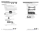
Figure 2-3 — MTPX Plus 128 rear panel
Inputs
C
Turn off power to the input and output devices, and
disconnect their power cords.
a
TP inputs — Connect up to 8, 16, or 32 (depending on
the matrix size) compatible TP inputs to the Inputs
RJ-45 connectors.
N
Configure the switcher for the appropriate input (RS-232
or audio) for each TP input. See "Defining the Audio/
RS-232 Wire Pair (and Configuring the Remote Port)" on
page 3-6.
b
Local RGB (VGA) inputs — Connect analog
computer video sources to the Local Inputs
15-pin HD female connectors.
N
These connectors can also accept HD component video,
component video, S-video, or composite video.
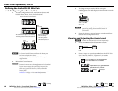
c
Local audio inputs — Connect balanced or unbalanced
stereo audio inputs to the Audio 5-pole captive screw
connectors.
L R
Unbalanced Input
Balanced Input
(high impedance) (high impedance)
Ring
Sleeve (s)
Tip
Sleeve
Tip
Sleeve
Tip
Tip
Ring
Do not tin
the wires!
Figure 2-4 — Audio input connector wiring
d
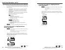
Input Select switches (switchers other than the
INPUT SELECT
ON
LOCAL
RJ - 45
1 2 3
MTPX Plus 128) — Set the Input Select DIP switches
for each input that can be either local or on TP cable
from an MTP transmitter.
RJ-45 (down) for an input from an MTP transmitter (
a
)
Local (up) for a local (RGB video and audio) input (
b and c
)
N
MTPX Plus 1616 and smaller have Input Select DIP
switches for inputs 1 through 3.
MTPX Plus 1632 and larger have Input Select DIP
switches for inputs 1 through 6.
MTPX Plus Series • Installation
Installation
MTPX Plus Series • Installation
2-3