


2-3MVX 44 / 48 / 84 / 88 VGA Matrix Switchers • Installation
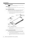
3. Drill 1/4" (6.4 mm) deep, 3/32" (2 mm) diameter pilot holes in the table or
desk at the marked screw locations from the underside/inside (concealed
side) of the furniture, where the switcher will be located.
4. Insert the four wood screws into the pilot holes. Fasten each screw into the
installation surface until just less than 1/4" of the screw head protrudes.
5. Align the installed screws with the slots in the mounting brackets, and place
the switcher against the surface, with the screws through the bracket slots.
6. Slide the switcher slightly forward or back, then tighten all four screws to
fasten it in place.
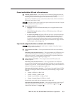
Cabling and Rear Panel Views
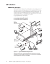
All connectors are on the rear panel. Depending on the model, the switcher can
have up to eight high resolution video and stereo audio inputs and eight video and
audio outputs.
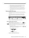
Figure 2-2 shows a MVX 88 VGA A video and audio switcher. Other switcher
models are housed in the same 1U enclosures, but have fewer input connectors
and/or output connectors to accommodate the different matrix sizes that they
provide.
100-240V 0.3A
50-60Hz
MVX 88 VGA A
RS-232
OUTPUTS
L
R
7
L
R
8
L
R
5
L
R
6
L
R
3
L
R
4
L
R
1
L
R
2
C
U S
LISTED
1T23
I.T.E.
1
2
3
4
INPUTS
5
6
7
8
1
2
3
4
OUTPUTS
3
4
5
6
7
8
3
5 4
1 2
INPUTS
Figure 2-2 — MVX 88 VGA A high resolution video switcher
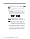
Video and audio input connections
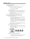
1
RGB video inputs — Connect the analog computer-video
sources to these 15-pin HD female connectors.
Most laptop or notebook computers have an external video port, but they require special
commands to output the video to that connector. Also, a laptop’s screen shuts off once that
port is activated. See the computer’s user’s guide for details, or contact Extron for a list of
common laptop keyboard commands.
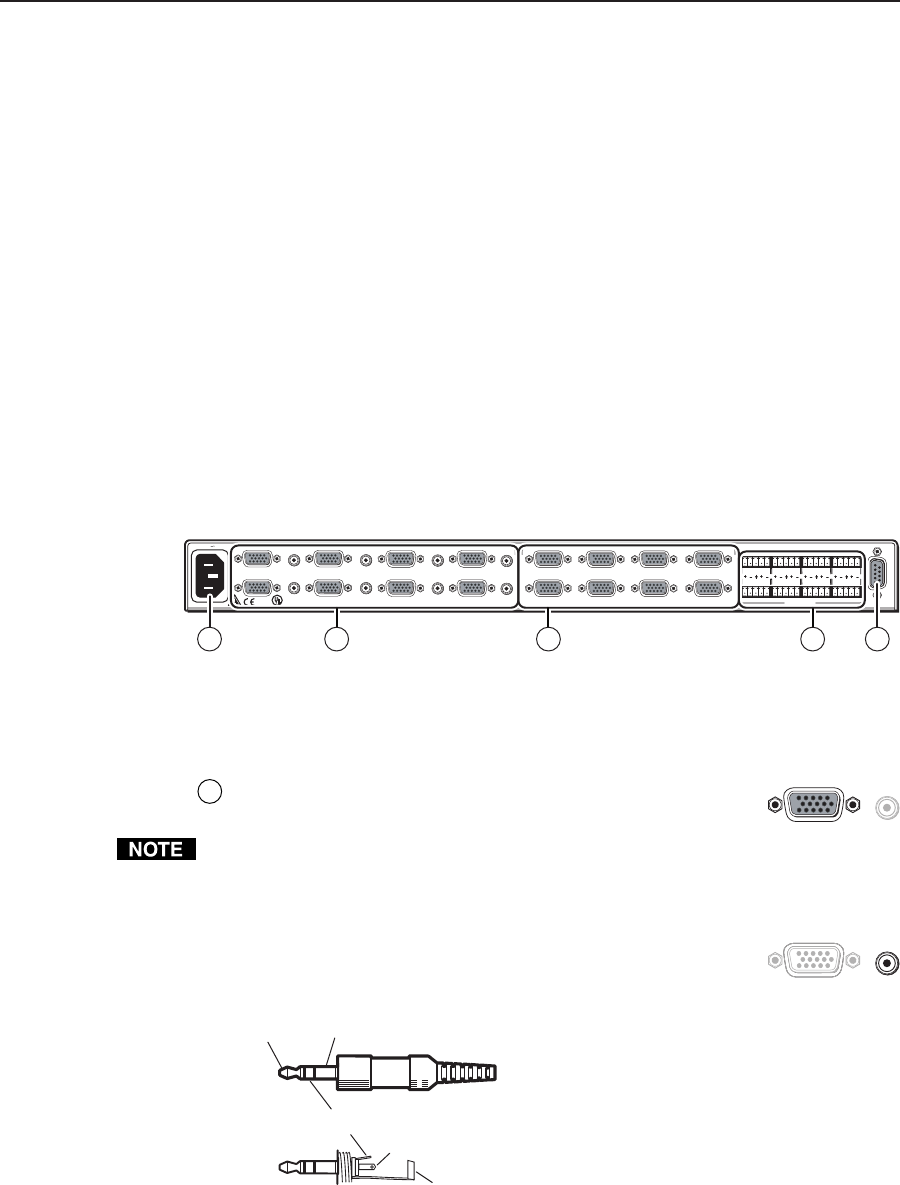
Audio inputs — Connect the unbalanced stereo audio sources
to these 3.5 mm mini stereo jacks for unbalanced audio input.
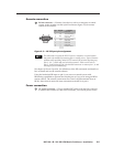
Figure 2-3 shows how to wire the audio plug.
Tip (L) Sleeve (Gnd)
Tip (L)
Ring (R)
Sleeve (Gnd)
Figure 2-3 — Audio input connector wiring
1
1