


3-5MVX 44 / 48 / 84 / 88 VGA Matrix Switchers • Operation
9
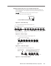
Audio Setup LED — The Audio Setup LED lights red to indicate that the
switcher is in Audio Setup mode. See Adjusting input audio gain and attenuation
on page 3-18.
Alternate IR error function — The Audio Setup LED also indicates errors
when you use an IR 501 small matrix remote control. The LED lights for
approximately 1 second when the switcher receives an unexpected or out-of-
sequence IR command from the remote control. The switcher otherwise
ignores the command.
10
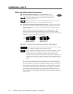
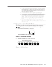
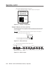
Down ( ) button and LED — The button decreases the audio gain for a
selected input. Press and release the button to decrease the gain by 1 dB or
press and hold the button to decrease the gain by 3 dB per second until the
button is released or the lower limit is reached.
On 4-output switchers, this button and LED stand alone.
On 8-output switchers, this button and LED are secondary functions of the
Output 7 button and LED.
The
LED flashes once in Audio Setup mode to indicate each 1 dB decrease in
the input audio gain. See Adjusting input audio gain and attenuation on
page 3-18.
The
LED lights steadily in Audio Setup mode to indicate that the
adjustment has reached the maximum attenuation (-18 dB).
11
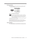
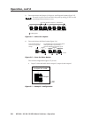
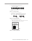
Up ( ) button and LED — The button increases the gain for a selected
input. Press and release the button to increase the audio level by 1 dB or press
and hold the button to increase the audio level by 3 dB per second until the
button is released or the upper limit is reached.
On 4-output switchers, this button and LED stand alone.
On 8-output switchers, this button and LED are secondary functions of the
Output 8 button and LED.
The
LED flashes once in Audio Setup mode to indicate each 1 dB increase in
the input audio gain. See Adjusting input audio gain and attenuation on
page 3-18.
The
LED lights steadily in Audio Setup mode to indicate that the
adjustment has reached the maximum gain (+10 dB).