


3-21MVX 44 / 48 / 84 / 88 VGA Matrix Switchers • Operation
a. If one or more output LEDs are lit AND the +dB LED is lit, press and
release the button repeatedly until the highest-numbered lit output
LED goes out. Count the button presses. In example 8, assume a value
of +8 dB. It will take three presses of the button for the Output 1 LED
to go out.
If one or more output LEDs are lit AND the –dB LED is lit, press and
release the
button repeatedly until the highest-numbered lit output
LED goes out. Count the button presses.
If the +dB LED is lit and NO output LEDs are lit, press and release the
button repeatedly until the +dB and –dB LED are both lit, indicating
0 dB. Count the button presses.
If the –dB LED is lit and NO output LEDs are lit, press and release the
button repeatedly until the +dB and –dB LED are both lit, indicating
0 dB. Count the button presses.
b. Return to the original audio gain setting by pressing and releasing the
or button (the opposite of the button you pressed in step a) the same
number of steps you pressed the opposite arrow button in step 1. In
example 8, this means pressing the button three times.
c. Add the dB value indicated by the highest-numbered lit output LED (no
output LEDs lit and both dB LEDs lit = 0 dB) and either of the following:
• The number of button presses from 0 dB, or
• The number of button presses from when the highest-numbered
output LED lit. In example 8:
Output 1 LED: 6 dB
+ 2 presses:
+2 dB
8 dB
d. The lit +dB or –dB LED indicates the gain (+) or attenuation (–).
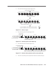
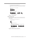
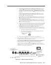
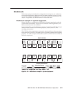
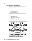
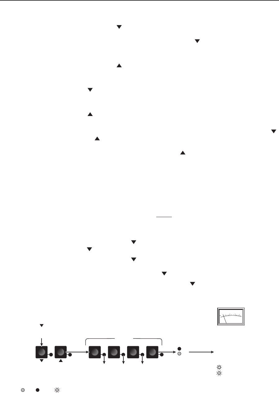
3. Press and release the
button once to decrease the audio level (figure 3-33).
The LED flashes each time the button is pressed
Press and release the
button several more times to continue to decrease the
audio level (figure 3-33). Note the output LED, +dB LED, and –dB LED
changes that occur each time the button is pressed and released.
Figure 3-33 shows the result of pressing the
button a total of 9 times to
change the value to -1 dB. Note that the +dB LED has turned off and that the
–dB LED is on to indicate a negative level.
VU
3
3
0
+
6
10
2
1
4
3
OUTPUTS
+dB
-dB
The -dB LED
indicates a negative
(attenuation) level.
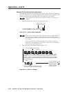
In this example, the LEDs indicate audio attenuation in the –1 dB to –5 dB range.
The Output 1, Output 2, and Output 3
LEDs display the input's audio level range.
Press the button to
decrease the input audio level
by 1 dB per button push.
The power LED blinks
frequently to indicate that
the adjusted level is
properly set.
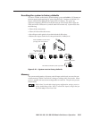
A VU meter connected
to output 1 indicates
that the adjusted level
is approximately the
same as the –10 dBV
internal level.
= lit, = unlit, = flickering LED
Figure 3-33 — Adjust the input audio level