


APPLICATION NOTE AN42
15
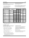
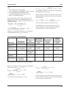
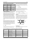
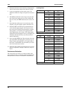
Table 10. Schottky Diode Selection Table
Output Filter Capacitors
Output ripple performance and transient response are
functions of the filter capacitors. Since the 5V supply of a PC
motherboard may be located several inches away from the
DC-DC converter, the input capacitance can play an impor-
tant role in the load transient response of the RC5040.
The higher the input capacitance, the more charge storage is
available for improving the current transfer through the
FET(s). Capacitors with low Equivalent Series Resistance
(ESR) are best for this type of application and can influence
the converter's efficiency if not chosen carefully. The input
capacitor should be placed as close to the drain of the FET as
possible to reduce the effect of ringing caused by long trace
lengths.
ESR is the resonant impedance of the capacitor, and it is dif-
ficult to quantify. Since the capacitor is actually a complex
impedance device having resistance, inductance, and capaci-
tance, it is natural for it to have a resonant frequency. As a
rule, the lower the ESR, the better suited the capacitor is for
use in switching power supply applications. Many manufac-
turers do not supply ESR data, but a useful estimate can be
obtained using the following equation:
where DF is the dissipation factor of the capacitor, f is the
operating frequency, and C is the capacitance in farads.
With this in mind, correct calculation of the output capaci-
tance is crucial to the performance of the DC-DC converter.
The output capacitor determines the overall loop stability,
output voltage ripple, and load transient response. The calcu-
lation is as follows:
where ∆V is the maximum voltage deviation due to load
transients, ∆T is the reaction time of the power source, and
I
O
is the output load current. ∆V is the loop response time of
the RC5040 and RC5042, approximately 8µs.
For I
O
= 10A and ∆V = 165mV, the bulk capacitance
required can be approximated as follows:
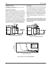
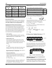
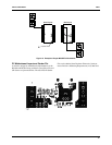
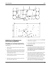
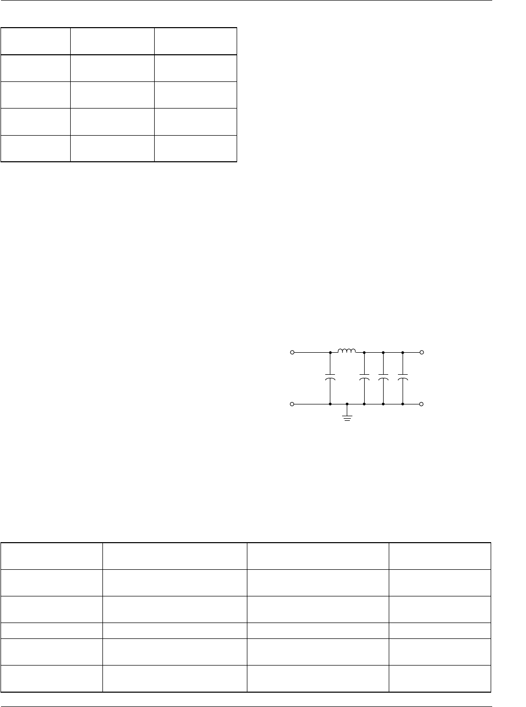
Input filter
The DC-DC converter design should include an input induc-
tor between the system +5V supply and the converter input
as described below. This inductor will serve to isolate the
+5V supply from noise occurring in the switching portion of
the DC-DC converter and also to limit the inrush current into
the input capacitors during power up. An inductor value of
around 2.5µH is recommended, as illustrated in Figure 15.
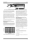
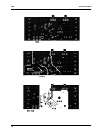
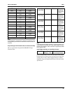
Bill of Materials
The Bill of Materials for the application circuits of Figures 2
through 4 is presented in Table 11.
Manufacturer
Model # Conditions
Forward Voltage
V
F
Philips
PBYR1035
I
F
= 20A; T
j
=25°C
I
F
= 20A; T
j
=125°C
< 0.84v
< 0.72v
Motorola
MBR2035CT
I
F
= 20A; T
j
=25°C
I
F
= 20A; T
j
=125°C
< 0.84v
< 0.72v
Motorola
MBR1545CT
I
F
= 15A; T
j
=25°C
I
F
= 15A; T
j
=125°C
< 0.84v
< 0.72v
Motorola
MBR2015CTL
I
F
= 20A; T
j
=25°C
I
F
= 20A; T
j
=150°C
< 0.58v
< 0.48v
ESR
DF
2
πfC
-------------=
C µF( )
I
O
∆T×
∆V I
O
ESR×–
--------------------------------------=
C µF( )
I
O
∆T×
∆V I
O
ESR×–
--------------------------------------
10A 8µs×
165mV 10A 11mΩ×–
--------------------------------------------------------- 1454µF= = =
1000µF, 10V
Electrolytic
0.1µF
65-AP42-17
2.5µH
5V Vin
Figure 15. Input Filter
Table 11. Bill of Materials for a 14.5A Pentium Pro Motherboard Application
C4, C5, C7, C8, C9,
C10
Panasonic
ECU-V1H104ZFX
0.1µF 50V capacitor
C6 Panasonic
ECSH1CY475R
4.7µF 16V capacitor
Cext Panasonic
ECU-V1H121JCG
39pF capacitor
C12
C1, C2, C3 United Chemicon
LXF16VB102M
1000µF 6.3V electrolytic
capacitor 10mm x 20mm
ESR<0.047Ω
C11 Panasonic
ECU-V1H224ZFX
0.22µF 50V capacitor