


APPLICATION NOTE AN42
9
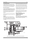
Converter Efficiency
Losses due to parasitic resistance in the switches, inductor,
and sense resistor dominate at high load-current levels. The
major loss mechanisms under heavy loads, in order of
importance, are:
• MOSFET I
2
R Losses
• Inductor Losses
• Sense Resistor Losses
• Gate-Charge Losses
• Diode-Conduction Losses
• Transition Losses
• Input Capacitor Losses
• Losses Due to the Operating Supply Current of the IC.
Efficiency of the converter under heavy loads can be calculated as follows:
,
where
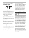
Design Equations:
, where
, where q
is the gate charge and f is the switching frequency
Efficiency
P
OUT
p
IN
--------------
I
OUT
V
OUT
×
I
OUT
V
OUT
P
LOSS
+×
---------------------------------------------------------= =
P
LOSS
PD
MOSFET
PD
INDUCTOR
PD
RSENSE
PD
GATE
PD
DIODE
PD
TRAN
PD
CAP
PD
IC
+ + + + + + +=
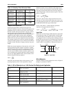
(1) PD
MOSFET
I
OUT
2
R
DS,ON
× DutyCycle×= DutyCycle
V
OUT
V
D
+
V
IN
V
D
V
SW
–+
------------------------------------------=
(2) PD
INDUCTOR
I
OUT
2
R
INDUCTOR
×=
(3) PD
RSENSE
I
OUT
2
R
SENSE
×=
(4) PD
GATE
q
GATE
f 5V××=
GATE
, where C
RSS
is the reverse transfer capacitance of the high-side MOSFET.
Example:
(5) PD
DIODE
V
f
I
D
× 1 DutyCycle–( )=
(6) PD
TRAN
V
IN
2
C
RSS
× I
LOAD
× f×
I
DRIVE
-------------------------------------------------------------=
(7) PD
CAP
I
RMS
2
ESR×=
(8) PD
IC
V
CC
I
CC
×=
DutyCycle
3.3 0.5+
5 0.5 0.3–+
------------------------------ 0.73= =
PD
MOSFET
10
2
0.030× 0.73× 2.19W= =
PD
INDUCTOR
10
2
0.010× 1W= =
PD
RSENSE
10
2
0.0065× 0.65W= =
PD
GATE
CV f× 5V× 1.75nf 9 1–( )V 650Khz 5V××× 0.045W= = =
PD
DIODE
0.5 10 1 0.73–( )× 1.35W= =
PD
TRAN
5
2
400pf× 10× 650khz×
0.7A
----------------------------------------------------------------
0.010W∼=
PD
CAP
7.5 2.5–( )
2
0.015× 0.37W= =
PD
IC
0.2W=