


APPLICATION NOTE AN42
21
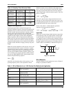
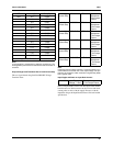
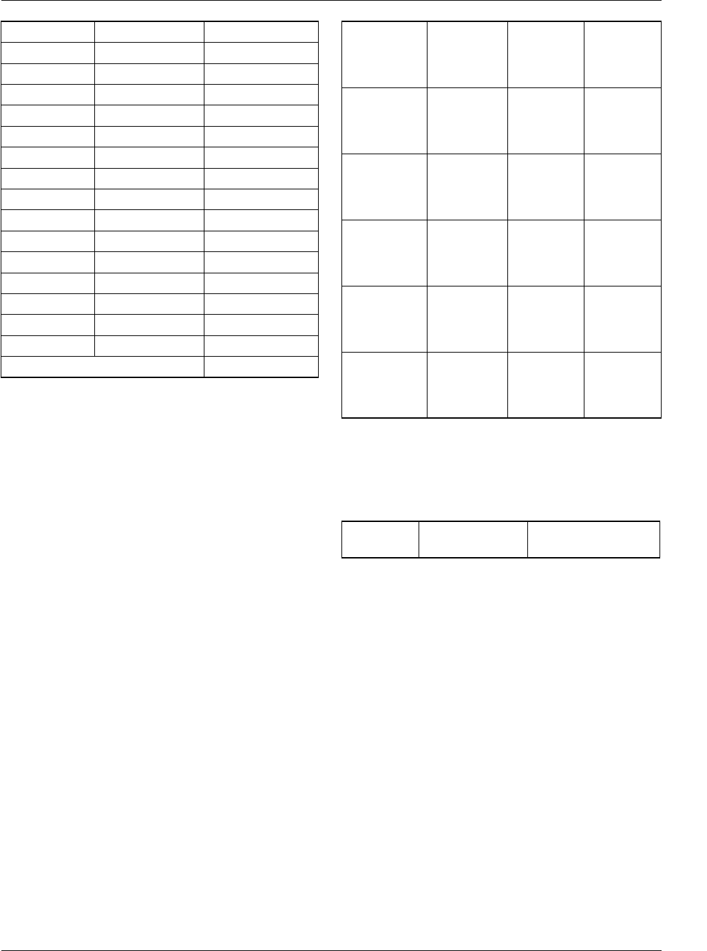
Note:
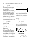
Load regulation is expected to be typically around 0.8%. The
load regulation performance for this device under evaluation is
excellent.
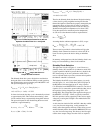
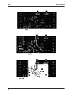
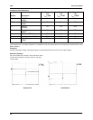
Output Voltage Load Transients Due to Load Current Step
This test is performed using Intel P6.0/P6S/P6T Voltage
Transient Tester.
Note:
Excellent transient voltage response. Transient voltage is rec-
ommended to be less than 4% of the output voltage. The per-
formance of the device under evaluation is significantly better
than a typical VRM.
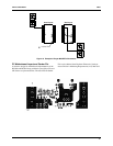
Input Ripple and Power on Input Rush Current
Power on Input Rush Current is not measured on the mother-
board because we did not want to cut the 5V trace and insert
current probe in series with the supply. However, with the
input filter design, the Input Rush Current will be well within
specification.
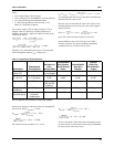
VID I
load
(A) V
out
(V)
1010 0.5 2.505
1.0 2.504
2.0 2.501
3.0 2.496
4.0 2.493
5.0 2.493
6.0 2.492
7.0 2.492
8.0 2.491
9.0 2.490
10.0 2.489
11.0 2.488
12.0 2.486
13.0 2.485
13.9 2.484
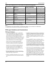
Load Regulation 0.5 - 13.9A 0.84%
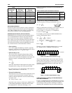
Low to High
Current Step
0.5A-9.9A - 76.0mV Refer to
Attachment
A for Scope
Picture
High to Low
Current Step
9.9A-0.5A + 70mV Refer to
Attachment
B for Scope
Picture
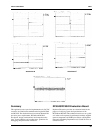
Low to High
Current Step
0.5A-12.4A - 97.6mV Refer to
Attachment
C for Scope
Picture
High to Low
Current Step
12.4A-0.5A + 80.0mV Refer to
Attachment
D for Scope
Picture
Low to High
Current Step
0.5A-13.9A - 99.2mV Refer to
Attachment
E for Scope
Picture
High to Low
Current Step
13.9A-0.5A + 105.2mV Refer to
Attachment
F for Scope
Picture
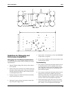
I
load
= 9.9A Input Ripple
Voltage = 15mV
Refer to Attachment
G for Scope Picture