


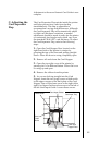
4. Always make very slight adjustments to the
Card Sensor, and run a test print after each
adjustment until the optimum chip position is
found. Also, after each adjustment, retighten the
screw loosened in step one.
Please refer to the following steps to adjust the
top-to-bottom position of the PolyGuard chip:
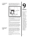
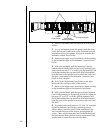
1. If the PolyGuard chips are being applied too
closely to, or overlapping, a cardÕs top or bottom
edge, the laminatorÕs Card Guide Rail should be
adjusted. To do this, simply loosen the two screws
which fasten the Card Guide Rail to the printerÕs
main chassis.
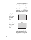
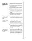
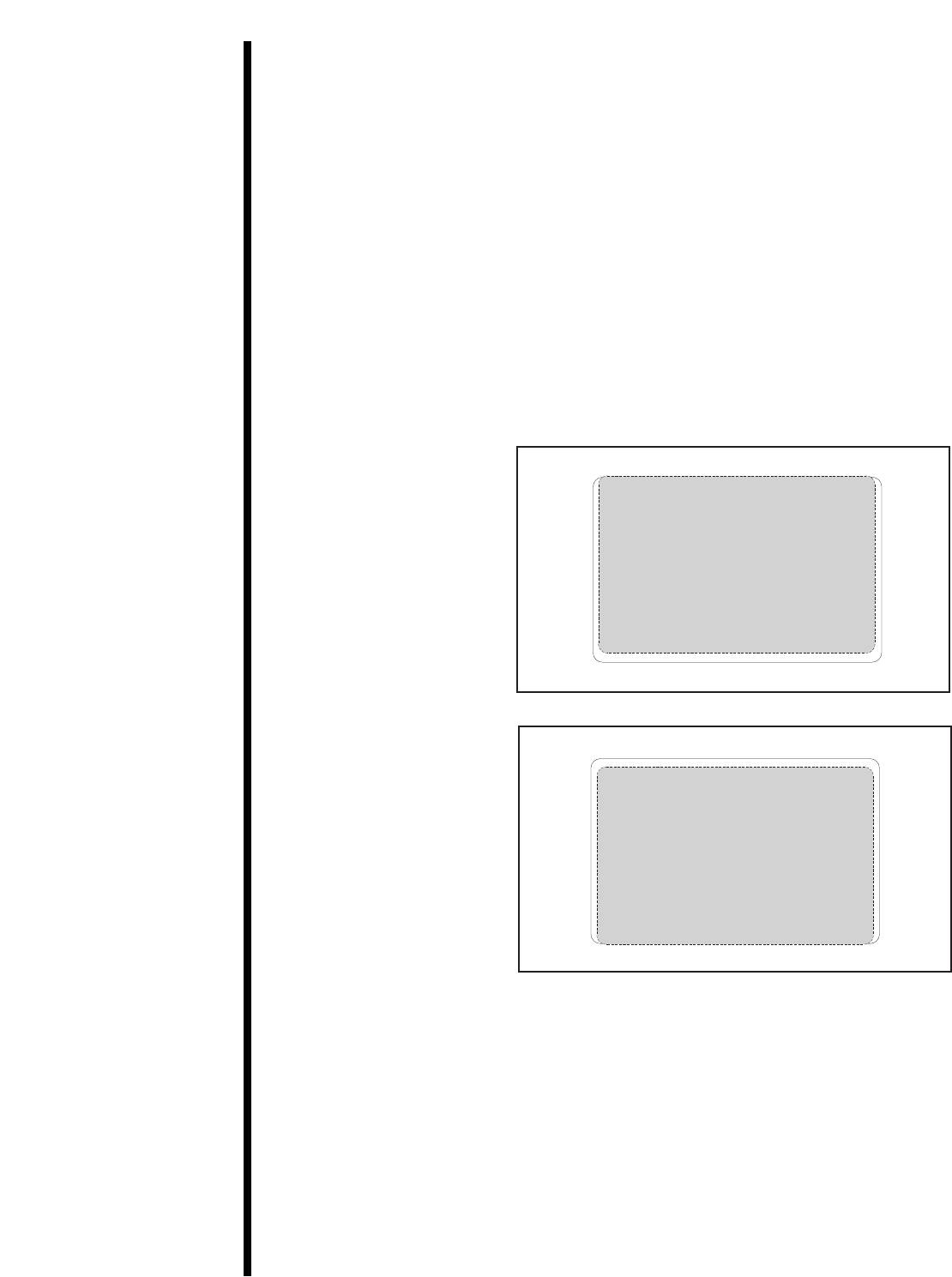
2. If the PolyGuard
chip is being placed
more toward a cardÕs
top edge (as shown),
move the Card Guide
Rail slightly toward the
rear of the printer
(opposite the direction
you would like the chip
to move).
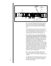
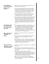
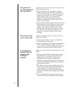
3. If the PolyGuard
chip is being placed
more toward a cardÕs
bottom edge (as shown),
move the Card Guide
Rail slightly toward the
front of the printer
(opposite the direction
you would like the chip
to move).
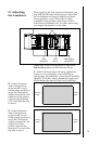
4. Always make very slight adjustments to the
Card Guide Rail, and run a test print after each
adjustment until the optimum chip position is
found. Also, be sure the Card Guide Rail always
remains parallel to the card path and that the
screws loosened in step one are retightened after
each adjustment.
52
Top Edge
Bottom Edge
Top Edge
Bottom Edge