FS-8700-101_Setra Model 370 Digital Pressure Gage Manual Page 6 of 23
FieldServer Technologies 1991 Tarob Court Milpitas, California 95035 USA Web:www.fieldServer.com
Tel: (408) 262-2299 Fax: (408) 262-9042 Toll_Free: 888-509-1970 email: support@fieldServer.com
3.1. Hardware Connection Tips / Hints
The following notes are extracted from the Setra 370 Operator Manual.
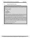
The Setra Digital Pressure Gage implements the majority of the RS-232 communications standard,
but does not provide handshaking lines (such as busy, DSR, or DTR). The four lines which must be
connected are diagrammed below, along with the pin layout of the female connector on the back of
the gage.
13 7 3 2 1
O O O O O O O O O O O O O
O O O O O O O O O O O O
25 14
Pin Desc.
1 Protective ground
2 Input to gage (RXD)
3 Output from gage (TXD)
7 Signal ground
The Model 370 serial interface is a DCE (Data Communications Equipment) type, with a standard
female DB25S pin connector. This means that it receives data on pin 2 and sends data on pin 3. This
is in contrast to DTE (Data Transmission Equipment) which receives data on pin 3 and sends data on
pin 2. The RS-232 standard describes communications between DTE and DCE devices.
Since many computers have serial ports configured as DTE, the Model 370 conveniently plugs
directly into the standard serial port on most computers, using a standard RS-232 "straight-through"
cable available from SETRA, or from any computer hardware vendor. Some devices, including some
printers and computers, will be equipped with DCE interfaces like that in the Model 370. To connect
the Model 370 to these devices, a "null modem" cable is required. This is simply a cable which
connects pin 2 and 3 of the Model 370 to pin 3 and 2 of the other device respectively by crossing
them in the cable. This kind of cable is also available from SETRA, or from any computer hardware
vendor.
The maximum recommended cable length is 15 meters.
The RS-232 data format used by the Model 370 is:
8 bits, 1 start bit, 1 stop bit, no parity.


