


FS-8700-112 FCI 7100 Series Driver Manual Page 17 of 24
FieldServer Technologies 1991 Tarob Court Milpitas, California 95035 USA Web:www.fieldserver.com
Tel: (408) 262-2299 Fax: (408) 262-9042 Toll_Free: 888-509-1970 email: support@fieldserver.com
Example:
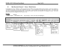
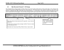
The following fragment is part of a Map Descriptor definition; some parameters have been omitted for the purposes of clarity.
Map_Descriptors
Data_Array_Name, Data_Array_Offset, Event Type, Point Type, Relay/Loop/Zone Number, Address, Length, Clear_on_reset, DA_Bit_Name
DA_MODU , 0, ANY, Module, 1, 1, 99, Yes, DB_MODU
DA_MODU_A, 0, ALARM, Module, 1, 1, 99, Yes, DB_MODU_A
DA_MODU_F, 0, FAULT, Module, 1, 1, 99, Yes, DB_MODU_F
DA_MODU_T, 0, TROUBLE, Module, 1, 1, 99, Yes, DB_MODU_T
DA_MPODU_O, 0, OTHER, Module, 1, 1, 99, Yes, DB_MODU_O
Message = “FAULT: AC Power 7100 0:00:04 1/01/92”
• This message does not report the status of a Zone, Relay, Loop, Sensor or Module and is therefore assumed to be a panel
message. Since there is no MD with “Point Type” Panel, the message is ignored.
Message = “TROUBLE: QZUb L1M22 << Chief's Office >> 5:24:00 3/03/93”
• This message reports status for Loop 1 Module 22. Since all the MD’s in the example have a ‘Point Type’=‘Module’, they are all
considered for storage.
• The driver looks in the Event Table and finds it has an index value of 34 and a category of 4 (Trouble). Only the MD’s with “Event
Type” set to “Any” and “Trouble” are now considered.
• Since the value of the ‘Relay/Loop/Zone’ parameter matches the Loop number in the message, these MD’s remain in contention.
• The Module number of 22 is compared with the MD’s Address and Length Parameters. The Address is the starting number and
the length defines the range. Both MD’s have addresses of 1 and length of 99 and thus both are still selected because the
Module of 22 falls in this range.
• The driver calculates an offset based on the offset specified in the MD and the Module number relative to the MD’s address:
MD Offset = 0
MD Address = 1
Message Module = 22
Module 1’s data is stored at offset 0 and hence Module 22’s data will be stored at offset 21. The driver stores the value 34 at
offset 21 overwriting any data previously stored at that location. This is ‘Index Value’ Storage.
• Seconday storage has been defined using the ‘DA_Bit_Name’ Data Array. The driver doubles the offset as two locations are used
for each address. Then the driver reads the value found in the Data_Array, modifies it and writes it back. As the index value is 34
the driver modifies the 34
th
bit – or expressed another way, the driver modifies the 2
nd
bit (34-32) at offset+1.
• Thus, driver calculates the offset for Bit Storage as 2 x 21 = 42. The driver sees that bit 34 is 2 2
nd
bit in the next offset and so the
driver reads DB_MODU:43, modifies the value by setting the 2nd bit on and then writing the modified value back. During the
modification all other bits are left intact. This using the Bit Storage method, a single Module (or sensor…) can keep track of
multiple events.