


Page 12 of 29FS-8700-66_GE-SNP Manual Page 12 of 29
FieldServer Technologies 1991 Tarob Court Milpitas, California 95035 USA Web:www.fieldServer.com
Tel: (408) 262-2299 Fax: (408) 262-2296 Toll_Free: 888-509-1970 email: support@fieldServer.com
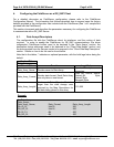
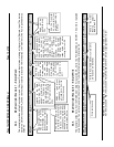
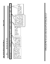
4.4.4. Map Descriptor Example 1 – Simple Read
This example provides a Map Descriptor to read 10 bytes of Discrete Input states, starting at the very first Discrete Input. The data is
stored in a Data Array called DA_DI and the first input is stored at location 100 in the array (101
st
element). The PLC is polled every 2
seconds
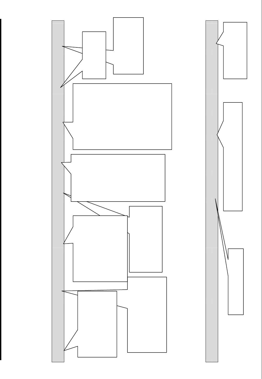
Map_Descriptor_Name,
Data_Array_Name,
Data_Array_Offset, Function,
Node_Name
Address
Length
Scan_Interval,
Data_Type
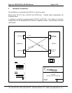
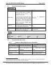
Read D1, DA_D1, 100, RDBC, PLC-1, 1, 10, 2.0, %1
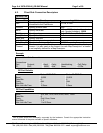
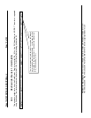
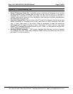
4.4.5. Map Descriptor Example 2 – Simple Write
This example writes data from the FieldServer Data Array called DA_AO to the PLC identified as NODE1. The write is repeated
every 5 seconds. Ten word values are written to the PLC’s %AQ Data Table starting at location 20.
Map_Descriptor_Name,
Data_Array_Name,
Data_Array_Offset, Function,
Node_Name
Address
Length
Scan_Interval,
Data_Type
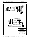
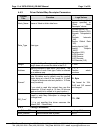
Write_AO, DA_AO, 0, WRBC, Node1, 20, 10, 5.0, %AQ
Use the % symbol
as you would if you
were programming a
GE PLC.
The name of the Data Array
in which the driver will store
the data. The name must
correspond to a Data Array
defined in the Data Array
section of the CSV file
Map Descriptor names
may be used in driver
error messages. It is not
essential, but it is useful
to use unique names.
RDBC = read block
continuous. The driver
will read data from the
PLC continuously.
The Node must
have been
defined in the
Nodes section of
the CSV file.
The Node Name
connects this
Map Descriptor
to a Node which
in turn connects
the Map
Descriptor to a
port.
The address and length
specify the first element
and the number of
elements that must be
read from the PLC’s
data tables. GE PLC’s
reference data tables
starting at element 1.
Unless otherwise
specified, the driver
reads bytes and words.
This Map Descriptor
reads bytes of data
covering %I1 to %I79
Read will be
performed every
2.0s.
Write to PLC Table element number 20 to
29 inclusive (10 elements)
Write continuously
Write to the %AQ
(Analog Output)
table in the PLC.
Location in the Data
Array where the first
element of data will be
stored. The arrays are
zero referenced so an
offset of 100 indicates
the 101
st
element of the
array.