


9
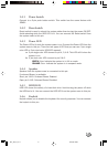
1.4.1 Power Switch
Connect to a 2-pin push button switch. This switch has the same feature with
JRMS1.
1.4.2 Reset Switch
Reset switch is used to reboot the system rather than turning the power ON/OFF.
Avoid rebooting while the HDD LED is lit. You can connect the Reset switch from
the system case to this pin.
1.4.3 Power LED
The Power LED is lit while the system power is on. Connect the Power LED from the
system case to this pin. There are two types of LED that you can use: 3-pin single
color LED or 2-pin dual color LED(ACPI request).
a. 3 pin single color LED connect to pin 4, 5, & 6. This LED will lit when the
system is on.
b. 2 pin dual color LED connect to pin 5 & 6.
GREEN Color: Indicate the system is in full on mode.
ORANGE Color: Indicate the system is in suspend mode.
1.4.4 Speaker
Speaker from the system case is connected to this pin.
If on-board Buzzer is available:
Short pin 14-15: On-board Buzzer Enabled.
Open pin 14-15: On-board Buzzer Disabled.
1.4.5 HDD LED
HDD LED shows the activity of a hard disk drive. Avoid turning the power off while
the HDD led is lit. You can connect the HDD LED from the system case to this pin.
1.4.6 Keylock
Keylock allows you to disable the keyboard for security purposes. You can connect
the keylock to this pin.
She_Chp1_01-11 19/1/00, 16:289