


User’s Manual 15
3. HARDWARE SETUP
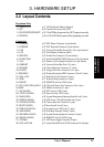
Layout Contents
3. H/W SETUP
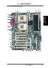
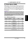
3.2Layout Contents
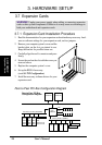
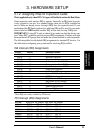
Expansion Slots
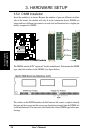
1)DIMM 0/1/2/3 p.17168-Pin System Memory Support
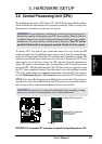
2)CPU p.19Central Processing Unit (CPU)
3)PCI1/PCI2/PCI3/PCI4/PCI7p.2032-bit PCI Bus Expansion Slots (PCI7 depends on model)
4)PCI5/PCI6 p.2064-/32-bit PCI Bus Expansion Slots (depending on model)
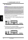
Connectors
1)PS2KBMS p.22PS/2 Mouse Connector (6-pin female)
2)PS2KBMS p.22PS/2 Keyboard Connector (6-pin female)
3)USB p.23Universal Serial Bus Ports 0 & 1 (Two 4-pin female)
4)LAN p.23Fast-Ethernet Connector (RJ45)
5)PRINTER p.23Parallel Port Connector (25-pin female)
6)COM1/COM2 p.23Serial Port COM1/COM2 Connectosr (Two 9-pin male)
7)VGA p.24Monitor (VGA) Output Connector (15-pin female)
8) USBPORT p.24Universal Serial Bus Port (10-1 pins)
9)CHASSIS p.25Chassis Intrusion Connector (4-1 pins)
10)FLOPPY p.25Floppy Disk Drive Connector (34-1 pins)
11)IDE1/IDE2 p.26Primary/Secondary IDE Connectors (Two 40-1 pins)
12)WOL_CON p.27Wake-On-LAN Connector (3 pins)
13)WOR p.27Wake-On-Ring Connector (2 pins)
14)IDELED p.28IDE/SCSI Activity LED (2 pins)
15)CPU_FAN1/2,CHA_FAN1/2p.28CPU and Chassis Fan Connectors (Four 3-pin)
16) SMB p.29SMBus Connector (5-1 pins)
17)NIC (PANEL) p.29NIC Activity LED (2 pins)
18)STATUS (PANEL) p.29Status Activity LED (2 pins)
19)SMI (PANEL) p.29System Management Interrupt Switch Lead (2 pins)
20)PWRSW (PANEL) p.30ATX Power / Soft-Off Switch Lead (2 pins)
21)CHASSIS (PANEL) p.30Chassis Intrusion Connector (2 pins)
22)RESET (PANEL) p.30Reset Switch Lead (2 pins)
23)PWR.LED (PANEL) p.30System Power LED Lead (3-1 pins)
24)NMI (PANEL) p.30Non-Mask Interrupt Switch (2 pins)
25)SPEAKER (PANEL) p.30System Warning Speaker Connector (4 pins)
26)IDELED (PANEL) p.30IDE/SCSI Activity LED (2 pins)
27)ATXPWR p.31ATX Power Supply Connector (20 pins)
28)SCSI-A/SCSI-B p.3168-pin Ultra160/Ultra2 SCSI Connectors (Two 68 pins)