


30 User’s Manual
3. HARDWARE SETUP
Connectors
3. H/W SETUP
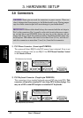
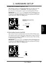
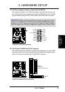
20)ATX Power Switch / Soft-Off Switch Lead (2-pin)
The system power is controlled by a momentary switch connected to this lead.
Pushing the button once will switch the system between ON and SLEEP or ON
and SOFT OFF, depending on your BIOS or OS setting. Pushing the switch
while in the ON mode for more than 4 seconds will turn the system off. The
system power LED shows the status of the system’s power.
21)Chassis Intrusion Lead (4-1 pin)
This requires an external detection mechanism such as a chassis intrusion moni-
tor/sensor or microswitch. The sensor is triggered when a high level signal is
sent to the Chassis Signal lead, which occurs when a panel switch or light detec-
tor is triggered. This function requires the optional CIDB chassis intru-
sion module to be installed (see 7. APPENDIX). If the chassis intrusion lead is
not used, a jumper cap must be placed over the pins to close the circuit.
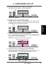
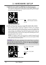
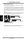
22)Reset Switch Lead (2-pin)
This 2-pin connector connects to the case-mounted reset switch for rebooting
your computer without having to turn off your power switch. This is a preferred
method of rebooting to prolong the life of the system’s power supply.
23)System Power LED Lead (3-1 pin)
This 3-1 pin connector connects to the system power LED, which lights when
the system is powered on and blinks when it is in sleep or soft-off mode. This
feature can be programmed through ASIC.
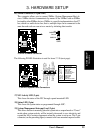
24)NMI Button (2-pin)
This 2-pin connector connects to a panel button to allow a non-mask interrupt
command to be sent to the operating system.
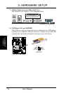
25)System Warning Speaker Connector (4-pin)
This 4-pin connector connects to the case-mounted speaker.
26)IDE Activity LED (2-pin)
This connector supplies power to the cabinet’s IDE activity LED. Read and
write activity by devices connected to the Primary or Secondary IDE connectors
will cause the LED to light up.