


User’s Manual 29
3. HARDWARE SETUP
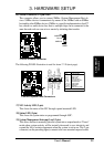
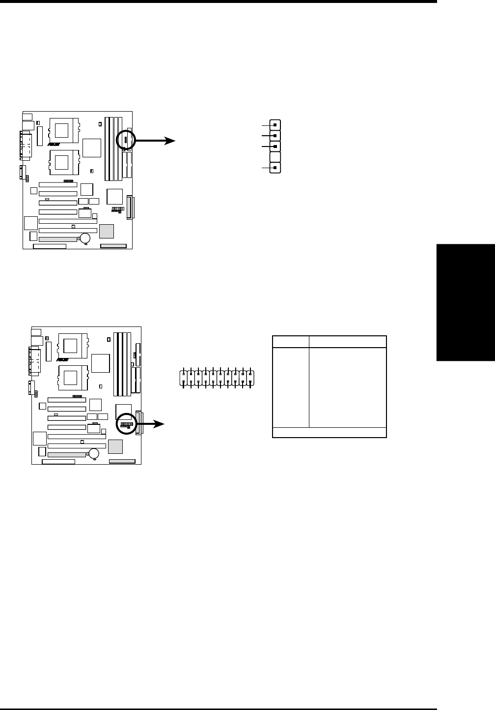
Connectors
3. H/W SETUP
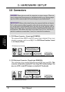
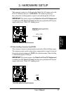
The following PANEL illustration is used for items 17–26 (next page).
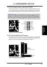
CUR-DLS System Panel Connectors
CUR-DLS
R
Chassis intrude
GND
SMI# buttton/sleep# button
NIC activity LED+
Power LED +
HDD access LED–
Status LED –
Status LED+
RESET button
GND
+5V
HDD access LED+
Power LED –
GND
Speaker
NIC activity LED–
Power button
GND
110
11 20
NMI button
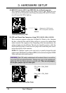
Pin Connector
1 & 12 NIC Activity LED
3 & 4 Status LED
4 & 5 SMI Lead
6 & 7* Power Button
7* & 8 Chassis Intrusion
9 & 10 Reset Switch
11 & 13 Power LED
15* & 16 NMI Button
17 & 20 Speaker
18 & 19 HDD Access LED
* Shared
Key
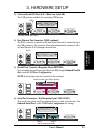
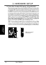
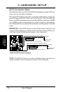
16)SMBus Connector (5-1 pin SMB)
This connector allows you to connect SMBus (System Management Bus) de-
vices. SMBus devices communicate by means of the SMBus with an SMBus
host and/or other SMBus devices. SMBus is a specific implementation of an I
2
C
bus, which is a multi-device bus; that is, multiple chips can be connected to the
same bus and each one can act as a master by initiating data transfer.
CUR-DLS SMBus Connector
CUR-DLS
R
1
SMB
SMBCLK
Ground
SMBDATA
+5V
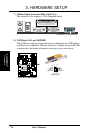
17)NIC Activity LED (2-pin)
This shows the status of the NIC through a panel-mounted LED.
18)Status LED (2-pin)
This shows the system status as programmed through ASIC.
19)System Management Interrupt Lead (2-pin)
This allows the user to manually place the system into a suspend mode or “Green”
mode where system activity will be instantly decreased to save electricity and
expand the life of certain components when the system is not in use. This 2-pin
connector (see the preceding figure) connects to the case-mounted suspend switch.