


User’s Manual 25
3. HARDWARE SETUP
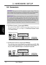
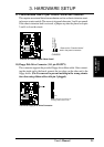
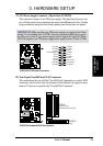
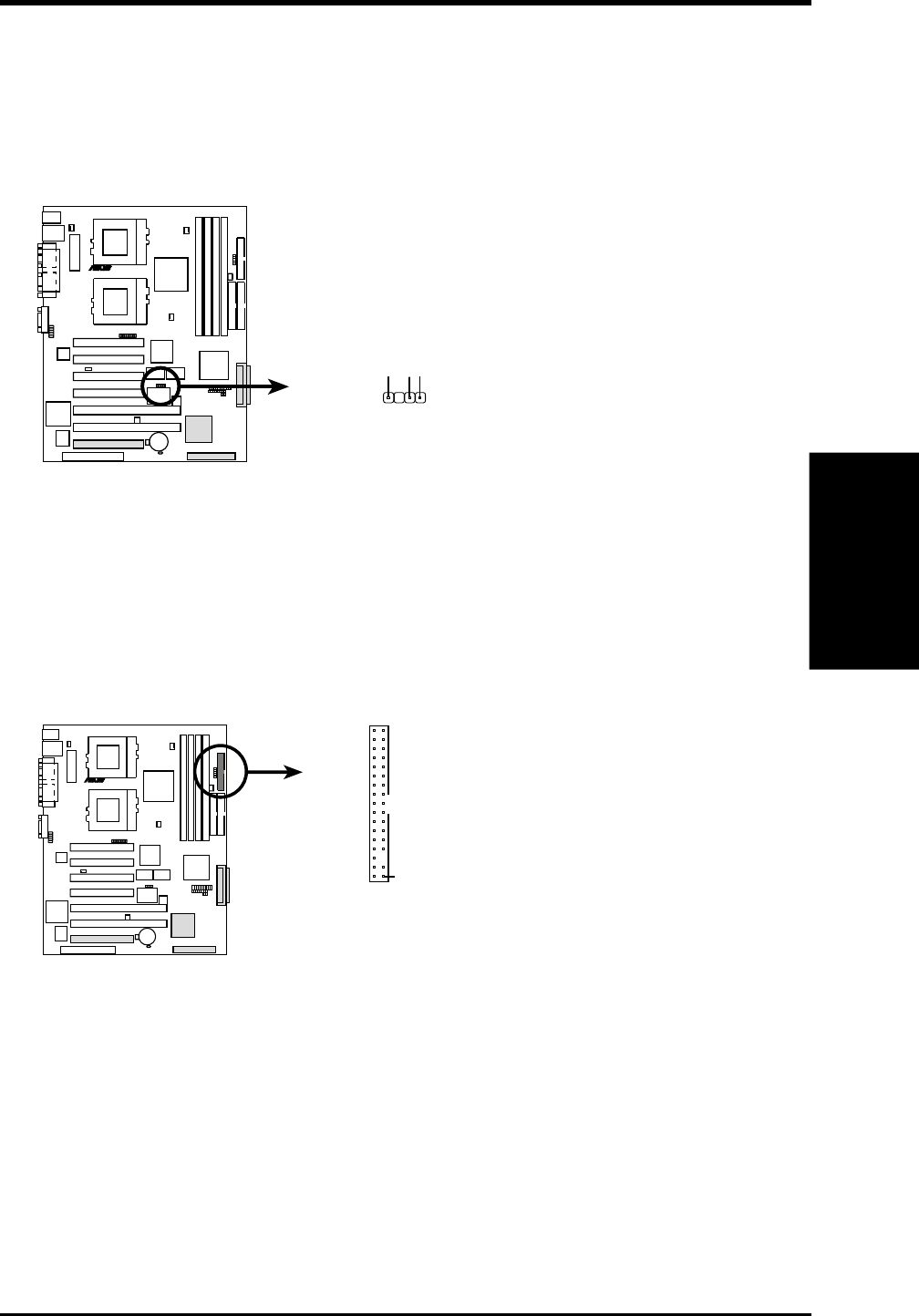
9)Chassis Intrusion Lead (4-1 pin CHASSIS) Also in Panel Connectors
This requires an external detection mechanism such as a chassis intrusion moni-
tor/sensor or microswitch. The sensor is triggered when pins 3 and 4 are opened.
If the chassis intrusion lead is not used, a jumper cap must be placed over pins
3 and 4 to close the circuit.
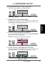
CUR-DLS Chassis Open Alarm Lead
CUR-DLS
R
Ground
Chassis Signal
3
CHASSIS
*Same as the “Chassis intrude”
lead in the panel connectors
4
(no connection)
1
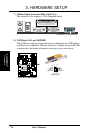
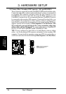
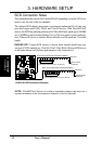
10)Floppy Disk Drive Connector (34-1 pin FLOPPY)
This connector supports the provided floppy drive ribbon cable. After connect-
ing the single end to the board, connect the two plugs on the other end to the
floppy drives. (Pin 5 is removed to prevent inserting in the wrong orienta-
tion when using ribbon cables with pin 5 plugged).
NOTE: Orient the red markings on
the floppy ribbon cable to PIN 1.
CUR-DLS Floppy Disk Drive Connector
PIN 1
CUR-DLS
R
Connectors
3. H/W SETUP