


User’s Manual 31
3. HARDWARE SETUP
Connectors
3. H/W SETUP
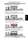
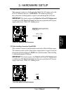
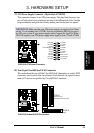
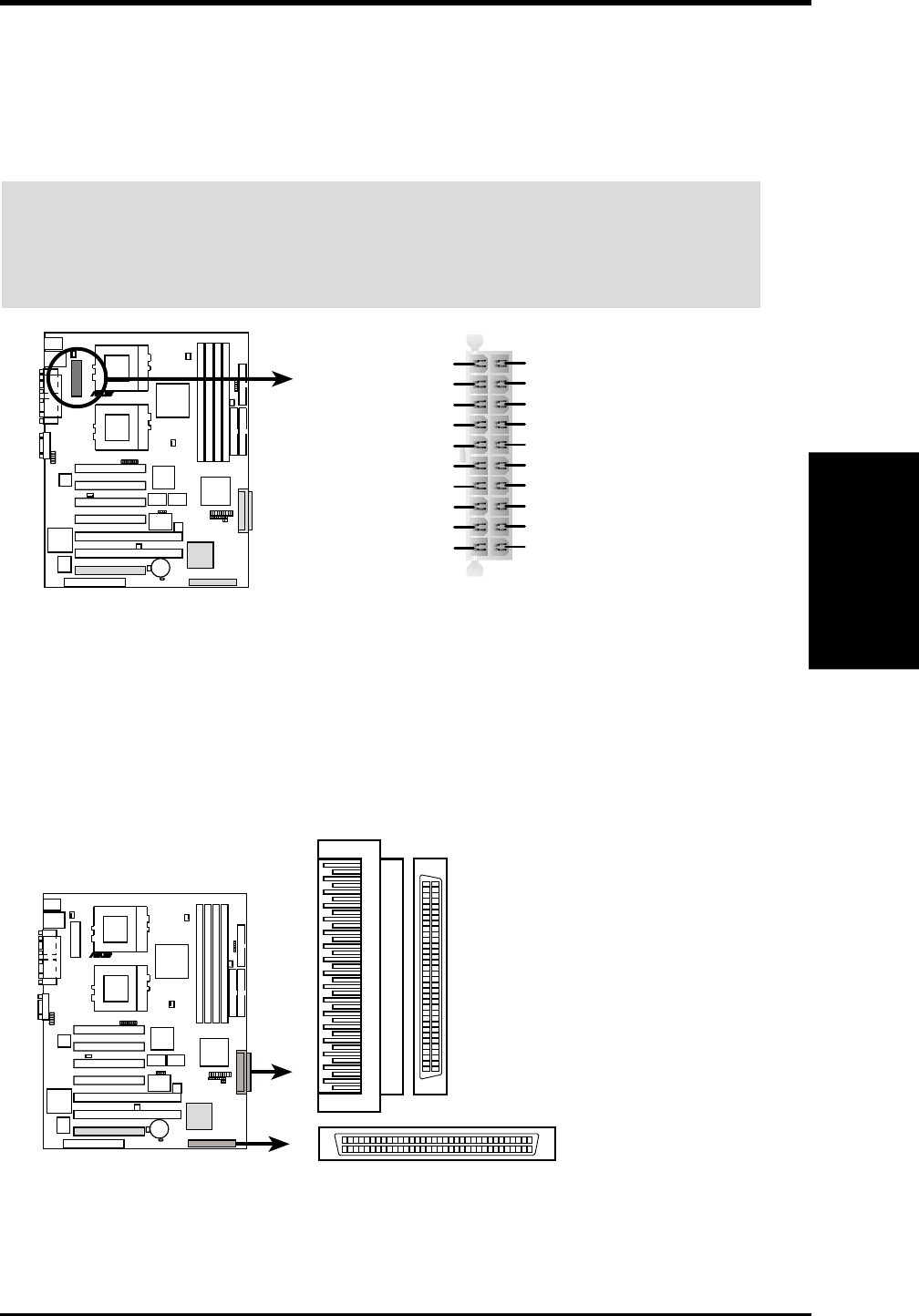
27)ATX Power Supply Connector (20-pin block ATXPWR)
This connector connects to an ATX power supply. The plug from the power sup-
ply will only insert in one orientation because of the different hole sizes. Find the
proper orientation and push down firmly making sure that the pins are aligned.
IMPORTANT: Make sure that your ATX power supply can supply at least 10mA
on the +5-volt standby lead (+5VSB). You may experience difficulty in power-
ing ON your system if your power supply cannot support the load. For Wake-
On-LAN support, your ATX power supply must supply at least 720mA +5VSB.
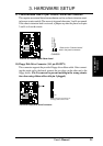
CUR-DLS ATX Power Connector
CUR-DLS
R
+3.3 Volts
-12.0 Volts
Ground
Power Supply On
Ground
Ground
Ground
-5.0 Volts
+5.0 Volts
+5.0 Volts
Power Good
+12.0 Volts
+3.3 Volts
+3.3 Volts
Ground
+5.0 Volts
Ground
+5.0 Volts
Ground
+5V Standby
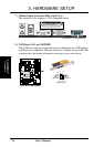
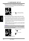
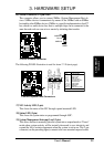
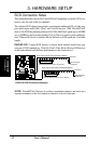
28)Two 68-pin Ultra160/Ultra2 SCSI Connectors
This motherboard has two 68-Pin Ultra160/Ultra2 (depending on model) SCSI
connectors; one for each of the two channels. Each channel can support a maxi-
mum of 15 devices as specified by Ultra160/Ultra2 standards.
CUR-DLS
R
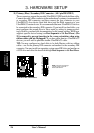
CUR-DLS Onboard SCSI Connectors
3568
34 1
35
6834
1
SCSI-B
68-Pin Ultra160/Ultra2-Wide SCSI Connector
SCSI-A
68-Pin Ultra160/
Ultra2-Wide SCSI Connector