5
Getting Started
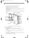
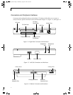
• PCMCIA Card Slot: Allows you to install PC Cards in the system.
†
• Charging contacts: Allows you to charge the battery pack and supply power to the Stylistic LT P-
600 in an optional mini-dock.
†
• Mini-dock interface: Allows you to install the Stylistic LT P-600 in an optional mini-dock
†
for
enhanced connectivity
• Reset button: Allows you to reset the system in the event of system difficulty. Note that pressing
this button results in loss of active data.
• Battery release switch: Used to release the removable battery pack.
• Compact flash slot: Used to accommodate a compact flash card.
• Memory cover: Removable cover over the RAM chips.
• Removable battery pack: Can be removed and charged in an optional external charger.
†
• Cooling vents: Provide secondary cooling for processor. (Do not obstruct the vents.)
†
These peripherals and accessories are sold separately.
Status Display 1
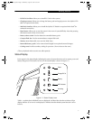
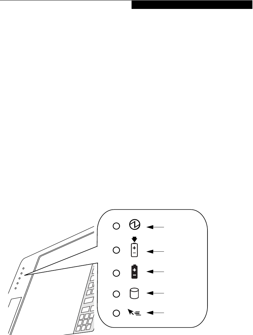
Icons appear in the Status display indicating the status of system functions such as system power and
battery charge level. The location of icons in the Status display is shown in Figure 1-3.
Figure 1-3 Status Display Icons
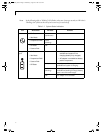
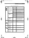
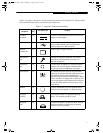
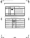
Table 1-1 explains how individual icons are displayed, and describes what the variations of that
display indicate. (If an icon is not displayed, it indicates that the related system function is off or
inactive.
Power
Charge/DC In
Battery
HDD Access
Hovering
58_0536_00.book Page 5 Wednesday, August 22, 2001 9:07 AM


