


SAS Interface
34 C141-C013
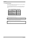
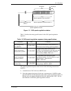
Table 1.5 OOB signal transmitter requirements
Signal Burst time Idle time Negation time
COMINIT/RESET 160 OOBI 480 OOBI 800 OOBI
COMSAS 160 OOBI 1440 OOBI 2400 OOBI
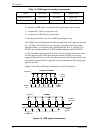
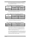
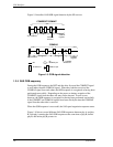
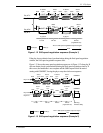
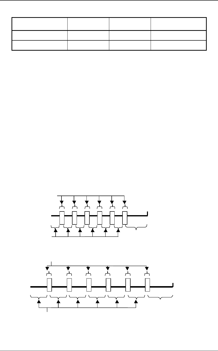
To transmit an OOB signal, a transmitter shall repeat these steps six times:
1) transmit D.C. idle for an idle time; and
2) transmit an ALIGN burst for a burst time.
It shall then transmit D.C. idle for an OOB signal negation time.
The ALIGNs used in OOB signals should be at generation 1 (G1) physical link rates
(i.e., 1,5 Gbps). The ALIGNs are only required to generate an envelope for the
detection circuitry, as required for any signaling that may be A.C. coupled. If G2
ALIGNs are used, the number of ALIGNs doubles compared with G1 ALIGNs.
A SAS transmitter should transmit ALIGNs at the G1 physical link rate to create
the burst portion of the OOB signal, but may transmit ALIGNs at its lowest
supported physical link rate if it is not able to transmit at the G1 physical link rate
and shall not transmit them at a physical link rate faster than its lowest supported
physical link rate.
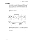
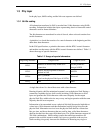
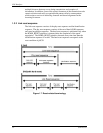
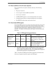
Figure 1.8 describes OOB signal transmission by the SP transmitter.
ALIGN burst
COMINIT
negation
COMSAS
negation
ALIGN burst
COMINIT
idle
COMSAS idle
COMRESET/COMINIT
COMSAS
COMINIT
Transmitt
COMSAS
Transmitted
1
2
3
4
5
6
1
2
3
4
5
6
1
2
3
4
5
6
1
2
3
4
5
6
Figure 1.8 OOB signal transmission