C156-E142-02EN 3 - 3
3.1.2 Temperature requirements and measuring method
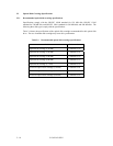
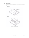
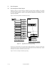
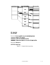
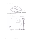
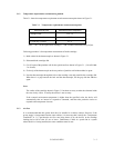
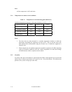
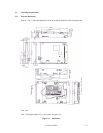
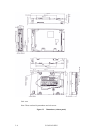
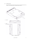
Table 3.1 shows the temperature requirement at each measurement point shown in Figure 3.1.
Table 3.1 Temperature requirements at measurement points
Measurement point Maximum surface temperature
Cartridge inside 55°C (*)
IC (controller) surface 95 °C
IC (read amp.) surface 85 °C
Note: * 60°C for the optical disk cartridge (1.3 GB excluded) manufactured by Fujitsu.
Following procedure is for temperature measurement of inside cartridge.
1) Make a hole for the thermocouple as shown in Figure 3.1.
2) Disassemble the cartridge disk.
3) Cut off a part of the partition wall for the optical media as shown in Figure 3.1. (Cut off width:
5 to 10 mm)
4) Fix the tip of the thermocouple to the cut portion of partition wall with an adhesive agent.
5) Pass the thermocouple through the hole at the cartridge case and assemble the cartridge disk.
When there is a gap between the hole and the thermocouple, fill the gap with the adhesive
agent.
Note:
The surface of the cartridge shown in Figure 3.1 has been cut away to make the elements inside
the case clearly visible. In reality the surface is not cut away.
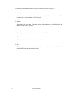
If the external environment temperature is higher than the specified value, the device will
automatically take an interval to respond to command, and then take protective action to
respond to the temperature increase.
3.1.3 Air flow
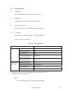
It is recommended that this optical disk drive be installed in a fanless cabinet. However, if the
power supply is incorporated into the same cabinet, it is necessary that it satisfy the “Temperature
Conditions” in 3.1.2 and that the air flow rate being drawn in by the device) at the cartridge
loading slot be 0.02 m
3
/min, 0.3 m/s or lower. Furthermore, if there is a system fan in a system
where this drive is being installed, the same conditions must be met.


