


C156-E142-02EN 4 - 5
4.3 Interface Registers
4.3.1 I/O registers
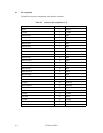
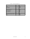
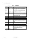
This section provides the I/O register functions and mapping. Definitions of each register vary
depending on which ATA or ATAPI commands are used.
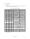
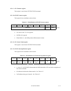
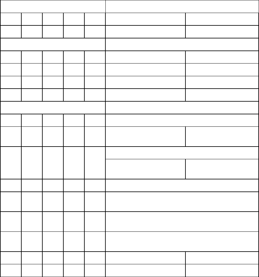
Table 4.4 I/O port functions and mapping
Address signal Function
CS0- CS1- DA2 DA1 DA0 READ (DIOR-) WRITE (DIOW-)
N N x x x High impedance state Ineffective
Control block register
N A 0 x x High impedance state Ineffective
N A 1 0 x High impedance state Ineffective
N A 1 1 0 Alternate Status Device Control
N A 1 1 1 Device Address Ineffective
Command block register
AN0 0 0 Data
A N 0 0 1 Error ATA Features (ATA)
ATAPI Features (ATAPI)
A N 0 1 0 Sector Count (ATA)
ATAPI Interrupt Reason
(ATAPI)
Ineffective
A N 0 1 1 Sector Number
A N 1 0 0 Cylinder Low (ATA)
ATAPI Byte Count (bits 0-7) (ATAPI)
A N 1 0 1 Cylinder High (ATA)
ATAPI Byte Count (bits8-15) (ATAPI)
A N 1 1 0 Device/Head (ATA)
ATAPI Block Device Select (ATAPI)
A N 1 1 1 ATAPI Status ATA Command
A A x x x Ineffective Ineffective
The letter A indicates that the bit is asserted, N indicates that the bit is negated, and X indicates
that the bit is ignored.