


7.4 Electrical Requirements
C156-E228-02EN 7-13
7.4.3 Signal driving conditions
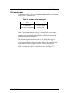
(1) Signal status value
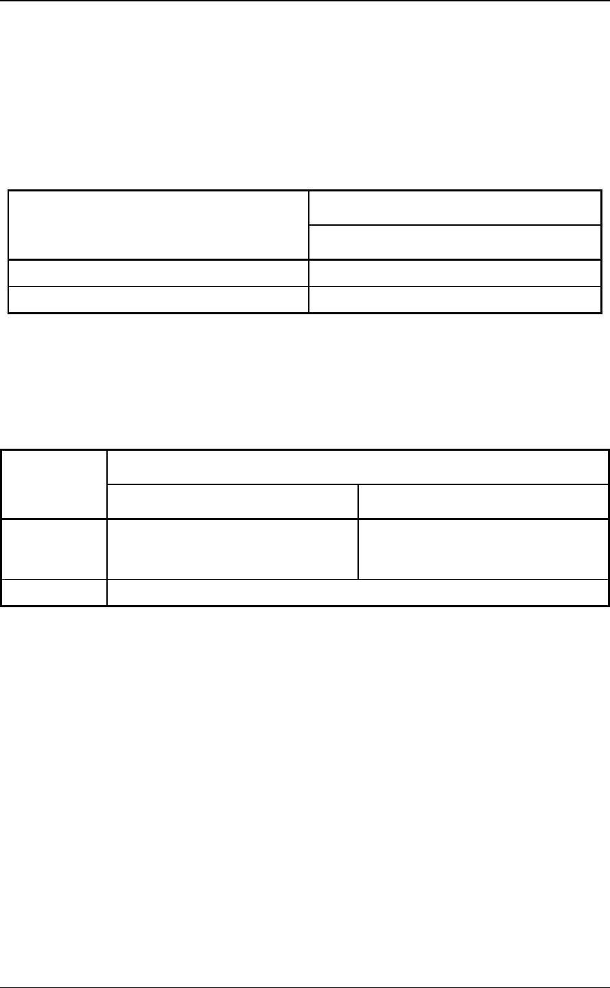
Table 7.4 shows the correspondence between the input interface signal level at the
receiving end and its logic state.
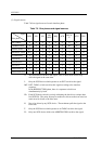
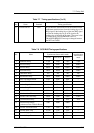
Table 7.4 Signal status
Signal level (at receiving end)
Logic state
Single-ended type
True, "1", or asserted Low (0.0 to 0.8 VDC)
False, "0", negated,, or released High (2.0 to 5.25 VDC)
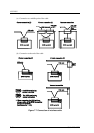
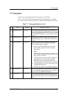
(2) Signal driving method
Two driving methods are available: "OR-tied" type and "non-OR-tied" type as
indicated in Table 7.5.
Table 7.5 Signal driving method
Signal status Driving method
"OR-tied" type "Non-OR-tied" type
False (*1) No SCSI device drives a signal. The
signal becomes false when the
terminating resistor circuit is biased.
A particular SCSI device drives the
signal false. Otherwise, no SCSI
device drives the signal.
True An SCSI device drives the signal true.
*1 In this manual, the signal is said to be false if one of the following
conditions is satisfied.
– The signal is actually driven by an SCSI device to become false (non-OR-
tied type).
– No SCSI device is driving the signal (OR-tied type or non-OR-tied type).
In the interface operating sequence, the driving method of the BSY and RST
signals which may be driven by two or more SCSI devices simultaneously must be
the "OR-tied" type. Signals other than BSY, RST, or DBP are not driven by more
than one SCSI device. Signals other than BSY or RST can be driven by either the
"OR-tied" type or "non-OR-tied" type. The DBP signal must not be driven false in
the ARBITRATION phase. For signals other than BSY or RST, both "OR-tied"
and "non-OR-tied" types can be mixed on the SCSI bus.