


21
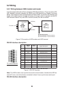
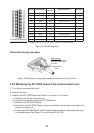
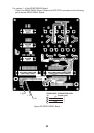
Pin (male) arrangement
.oNniPlangiS944-SR
TTICC
tiucriC
noitpircseDlangiSETD-ECD
22/4DS301ataDdneS
←
32/5TCS411gnimiTdneS
→
42/6DR401ataDevieceR
→
52/7STR501dneSottseuqeR
←
62/8RCS511gnimiTevieceR
→
72/9STC601dneSotraelC
→
92/11RSD701ydaeRteSataD
→
03/21RTD801ydaeRlanimreTataD
←
13/31DCD901ydaeRrevieceR
→
51CI521llaCgnimocnI
→
91GS201dnuorGlangiS–
Pin nos. 1-3, 10, 14, 16-18, 20-21, 28, 32-37 are not used.
Figure 15 RS-449 Interface
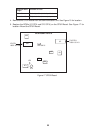
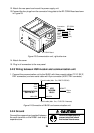
Fabrication of plug case assy.
Aluminum tape
Fold back braided shield
onto cable; tape shield
as shown.
Cable
Cable Clamp
Figure 16 Fabrication of plug case (same procedure for 25 pin, 37 pin)
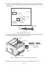
5.2.2 Modifying the RF CONV board in the communication unit
1. Turn off the communication unit.
2. Detach the cover.
3. Replace the RF CONV Board as follows if it is version -4 or below.
a) Unfasten the coaxial connector nut.
b) Unplug all connectors from the RF CONV Board.
c) Dismount the RF CONV Board.
d) Mount the new RF CONV Board, plug in connectors to the board, and fasten the
coaxial connector nut.
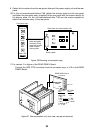
e) For the new RF CONV Board, set R135 according to antenna cable length as shown
in the table below. See Figure 19 for the location of R135.