


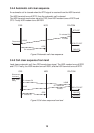
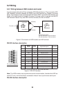
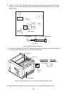
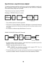

6. Version -1 of the CPU 2 Board, solder a harness of cable assy. (supplied) to the loca-
tion shown in the illustration below. Connect other side of cable assy. to J10 on the RF
CONV board.
U65
U67
DIP SW S1
JP2
BT1
C75
U37
U8
U5
CPU2 BOARD 16P0133
U55
7
U56
GND
HSD ON
12
Part side
RF CONV Board
CPU2 Board
U567
U55
PH5P
J10
1
2
4
1
Cable assy.
12
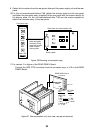
Figure 18 CPU 2 Board Version 1
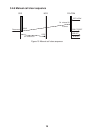
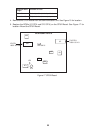
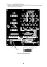
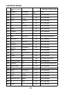
7. For version -2 and after of the CPU2 Board, connect the cable assy. (supplied) between
J7 on the CPU2 Board and J10 on the RF CONV Board.
INMARSAT-B
MOBILE EARTH STATION
COMPASS
BEARING
ELEVATION
S LEVEL
TEL 1
TEL 2
TEL 3
TEL 4
TEL 5
TEL 6
TELEX
DATA
AOR-WEST
AOR- EAST
POR
POWER
DIMMER
LOCK
I
OR
READY
TX
FAIL
FELCOM 81
DIMMER
LOCK
DIMMER
LOCK
INMARSAT-B
MOBILE EARTH STATION
COMPASS
BEARING
ELEVATION
S LEVEL
TEL 1
TEL 2
TEL 3
TEL 4
TEL 5
TEL 6
TELEX
DATA
AOR-WEST
AOR- EAST
POR
POWER
DIMMER
LOCK
I
OR
READY
TX
FAIL
R135
CPU2 Board
Cable assy.
J10
Marked
point
J7
RF CONV Board
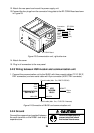
RF CONV Board CPU2 Board
J10 (PH2P) J7 (PH5P)
1 GND 1 P20 (HSD ON)
2 HSD ON 2 P21
3 P23
4 GND
5
Figure 19 Communication unit, cover removed, right side view
8. Replace the rear panel for the communication unit manufactured before 7/98.
23