


26
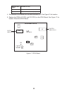
12. Attach the rear panel and mount the power supply unit.
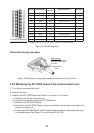
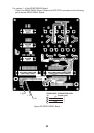
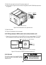
13.Connect the four plugs from the connector fixing plate to the RF CONV Board as shown
in Figure 23.
INMARSAT-B
MOBILE EARTH STATION
COMPASS
BEARING
ELEVATION
S LEVEL
TEL 1
TEL 2
TEL 3
TEL 4
TEL 5
TEL 6
TELEX
DATA
AOR-WEST
AOR- EAST
POR
POWER
DIMMER
LOCK
I
OR
READY
TX
FAIL
FELCOM 81
DIMMER
LOCK
DIMMER
LOCK
INMARSAT-B
MOBILE EARTH STATION
COMPASS
BEARING
ELEVATION
S LEVEL
TEL 1
TEL 2
TEL 3
TEL 4
TEL 5
TEL 6
TELEX
DATA
AOR-WEST
AOR- EAST
POR
POWER
DIMMER
LOCK
I
OR
READY
TX
FAIL
J7
J9
J8
Connector RF CONV
assy. Board
TX IF J9
RX IF J7
REF J8
(DGPS (J11)
OUT)
RF CONV Board
J11
Figure 23 Communication unit, right side view
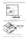
14. Attach the cover.
15. Plug in all connectors to the rear panel.
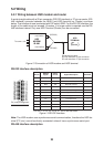
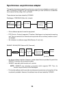
5.2.3 Wiring between HSD modem and communication unit
1. Connect the communication unit to the IB-681 with three coaxial cables (TX IF, RX IF,
REF connectors) and one serial cable with 9 pin connector (HSD CTRL connector).
COMMUNICATION
UNIT IB-281
HSD
MODEM
IB-681
TX IF
RX IF
REF
HSD CTRL
TX IF
RX IF
REF
HSD CTRL
Serial cable (Max. 5 m, 17JE-573-2 harness)
Coaxial cable (Max. 5 m, BNC-P-55UX2)
Ship’s
mains
16S0277
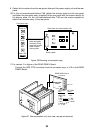
Figure 24 Connection of IB-681 and communication unit
5.2.4 Ground
Connect the copper strap (supplied) between
the earth terminal on the IB-681 and ship’s
superstructure.
Ground the equipment to
prevent electrical shock
and mutual interference.
CAUTION