


Magnum 6K25 Managed Fiber Switch Installation and User Guide (04/06)
9
www GarrettCom com
..
LEDs in the front and the power input and management console connector in the rear) or
“Reverse” (with the ports and LEDs and the power-input and the management console
connector all in the rear and a duplicate set of LEDs in the front). Rack widths
accommodated include standard 19” RETMA, ETSI, and 23” Telco. Input power may be
AC, or –48VDC for Telco environments, or 24VDC for Industrial applications.
Designed for use in network traffic centers, the Magnum 6K25 Managed Fiber
Switches are easy to install and use. Addresses of attached nodes are automatically
learned, maintained and aged out, adapting the switching services to network changes.
LEDs provide status information on each port. The Magnum 6K25 provides high
performance plug-and-play hardware operation, 802.1p packet prioritization in hardware,
and industry-standard managed networks software functionality, all in convenient 1U
rack-mount packages.
2.2.1 Magnum 6K25 and 6K25R chassis
The Magnum 6K25 is a 19” rack-mountable Ethernet Switch with three eight-
port slots (A, B, and C) and one Gb-only slot (D) for configuration flexibility. Slots A, B
and C may be configured with any of a large selection of fiber and copper port types and
combinations of types, typically eight ports per module, but sometimes 6 or 4 ports or
even one Gb port. Slot D may be configured with a Gb module that accepts GBICs. The
port types configurable using the 4 slots allows the 6K25 to efficiently serve a large
variety of applications, especially using fiber media. The Magnum 6K25 port modules
are normally factory installed, but may be changed or added in the field. (See Section 5)
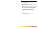
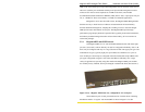
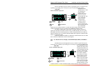
Figure 2.2.1a: “Regular” 6K25 front view, configured for 24 +1 Gb ports
Status LEDs are part of each port module and are viewable when connecting
the Ethernet media. A “regular” rack-mount 6K25 is shown in Figure 2.2.1a. On