


Magnum 6K25 Managed Fiber Switch Installation and User Guide (04/06)
49
www GarrettCom com
..
and will allow both unshielded twisted pair (UTP) and shielded twisted pair (STP) cable
connections. The 6KP8-RJ45 module is equipped with a Media Dependent Auto-
Crossover (MDI-X) switch, which controls all ports for cascaded connection. This
feature eliminates the need for a special twisted pair crossover cable when connecting to
a hub or another switch.
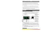
Each port has an Activity (ACT) LED indicating packets being received, a
Link (LK) LED that indicates proper connectivity with the remote device when lit, a
FDX/HDX LED to indicate full-duplex mode when lit (or half-duplex when off), and a
“10/100” LED indicating 100Mb when lit (or 10 Mbps when off).
Important Note: The 10/100 RJ-45 ports are supported with Auto-negotiation and
Auto-crossover (MDIX), which allow the RJ-45 ports to automatically Link with any RJ-
45 device and eliminate the use of cross-over cable.
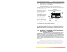
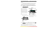
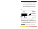
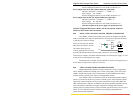
5.2.10 New PoE(Power Inside), model PI6KP8-45RJ (MDIX), 10/100Mb 8-port
The PoE RJ-45 ports act similar to regular RJ-45 ports, except they have
capability of providing power on each port to power up the PD devices, per the
IEEE802.3af PoE
standard. Only 4 x RJ-
45 (10/100) ports
maxm. support
POE(Power Inside)
option in one 6K-unit.
In this Fig. the top 4-
RJ45 ports are
enhanced with POE
option whereas as
bottom 4- RJ-45 are
normal MDIX ports.
The 4-RJ45 POE
module are also
available with mix –n-
match with fiber modules. Please check the ordering information Sec.1.2. for all the
various PI6K PoE modules option.
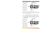
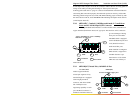
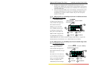
The LEDs on 6KP8-RJ45- PoE module are slightly different compared to
regular (non-PoE) RJ-45 modules as shown in Fig 2. When the PoE port is in use, the
PoE LED is ON when connected properly to a 803.af compliant PD device on that port.
When non-PoE devices are connected, the PoE LED is OFF. Operation of Ethernet data
traffic is not affected by PoE.
LINK and ACTIVITY LEDS are combined on the PoE modules into one LED
that is marked as LINK/ACT, as shown in the diagram.
PoE LEDs Summary
For PoE devices, each RJ-45 PoE port supports only 802.3af complaint
6KP8-45RJ
8 Port@ 10/100Mb Copper ports
4
4
FULL/HALF
1
PoE
LINK
LK
/
ACT
2
3
10/10
2
1 3 5
10/10
LK/AC
1
3
F/H
POE
10/10
LK/AC
2 4 6
F/ H
POE